TS 38.415
NG-RAN —
PDU Session User Plane protocol
V18.1.0 (PDF)
2024/03 24 p.
V17.1.0
2023/12 19 p.
V16.6.0
2021/12 18 p.
V15.3.0
2021/06 14 p.
- Rapporteur:
- Mr. Godin, Philippe
Nokia France
Content for TS 38.415 Word version: 18.1.0
1 Scope
2 References
3 Definitions and abbreviations
4 General
5 PDU Session user plane protocol
5.1 General
5.2 PDU Session user plane protocol layer services
5.3 Services expected from the Transport Network Layer
5.4 Elementary procedures
5.5 Elements for the PDU Session user plane protocol
5.6 Handling of unknown, unforeseen and erroneous protocol data
6 PDU Set Information user plane protocol
6.1 General
6.2 PDU Set Information user plane protocol layer services
6.3 Services expected from the Transport Network Layer
6.4 Elementary procedures
6.5 Elements for the PDU Set Information user plane protocol
6.6 Handling of unknown, unforeseen and erroneous protocol data
A Example of using Future Extension Field
$ Change history
1 Scope p. 6
The present document specifies the PDU Session user plane protocol being used over the NG-U, Xn-U and N9 interfaces. Applicability to other interfaces is not precluded.
The present document also specifies the PDU Set Information user plane protocol being used over the NG-U, Xn-U, F1-U and N9 interfaces. Applicability to other interfaces is not precluded.
2 References p. 6
The following documents contain provisions which, through reference in this text, constitute provisions of the present document.
- References are either specific (identified by date of publication, edition number, version number, etc.) or non-specific.
- For a specific reference, subsequent revisions do not apply.
- For a non-specific reference, the latest version applies. In the case of a reference to a 3GPP document (including a GSM document), a non-specific reference implicitly refers to the latest version of that document in the same Release as the present document.
[1]
TR 21.905: "Vocabulary for 3GPP Specifications".
[2]
TS 38.300: "NextGen Radio Access Network (NG-RAN); Overall description; Stage 2".
[3]
TS 29.281: "General Packet Radio System (GPRS) Tunnelling Protocol User Plane (GTPv1-U)".
[4]
TS 37.324: "E-UTRA and NR; Service Data Application Protocol (SDAP) specification".
[5]
TS 23.501: "System Architecture for the 5G System; Stage 2".
[6]
RFC 5905 (2010-06): "Network Time Protocol Version 4: Protocol and Algorithms Specification".
[7]
TS 38.413: "NG-RAN; NG Application Protocol (NGAP)".
[8]
TS 38.470: "NG-RAN; F1 general aspects and principles".
[9]
TS 38.401: "NG-RAN; Architecture Description".
3 Definitions and abbreviations p. 6
3.1 Definitions p. 6
For the purposes of the present document, the terms and definitions given in TR 21.905 and the following apply. A term defined in the present document takes precedence over the definition of the same term, if any, in TR 21.905.
gNB-CU:
as defined in TS 38.401.
gNB-DU:
as defined in TS 38.401.
Multicast Broadcast User Plane Function:
as defined in TS 23.501.
NG-U:
as defined in TS 38.300.
Xn-U:
logical interface between NG-RAN nodes as defined in TS 38.300.
Data Burst:
as defined in TS 23.501.
PDU Set:
as defined in TS 23.501.
F1-U:
logical interface between gNB-CU and gNB-DU as defined in TS 38.470.
3.2 Abbreviations p. 7
For the purposes of the present document, the abbreviations given in TR 21.905 and the following apply. An abbreviation defined in the present document takes precedence over the definition of the same abbreviation, if any, in TR 21.905.
DL
Downlink
MBS
Multicast Broadcast Service
MB-UPF
Multicast Broadcast User Plane Function
PDCP
Packet Data Convergence Protocol
PPI
Paging Policy Indicator
PPP
Paging Policy Presence
QFI
QoS Flow Identifier
RQA
Reflective QoS Attribute
RQI
Reflective QoS Indication
SN
Sequence Number
UL
Uplink
UP
User Plane
UPF
User Plane Function
EPDU
End PDU of the PDU Set
EDB
End of Data Burst
PSI
PDU Set Importance
PSSN
PDU Set Sequence Number
PSN
PDU Sequence Number within a PDU Set
PSSize
PDU Set Size
4 General p. 7
4.1 General aspects p. 7
The PDU Session User Plane protocol and PDU Set Information User Plane protocol are located in the User Plane of the Radio Network Layer above the Transport Network Layer of the interface.
Each PDU session User Plane protocol instance and PDU Set Information User Plane protocol instance are associated to one PDU Session.
In this version of the specification, the PDU Session User Plane protocol data is conveyed by GTP-U protocol means, more specifically, by means of the "PDU Session Container" GTP-U Extension Header as defined in TS 29.281.
In this version of the specification, the PDU Set Information User Plane protocol data is conveyed by GTP-U protocol means, more specifically, by means of the "PDU Set Information Container" GTP-U Extension Header as defined in TS 29.281.
5 PDU Session user plane protocol p. 7
5.1 General p. 7
The PDU session UP layer uses the services of the Transport Network Layer in order to send its packets over the interface.
5.2 PDU Session user plane protocol layer services p. 8
The following functions are provided by the PDU Session User Plane protocol:
- Provision of control information elements (e.g. QFI, RQI) associated with a PDU session.
5.3 Services expected from the Transport Network Layer p. 8
The PDU session UP layer expects the following services from the Transport Network Layer:
- Transfer of PDU session User Plane PDUs.
5.4 Elementary procedures p. 8
5.4.1 Transfer of DL PDU Session Information p. 8
5.4.1.1 Successful operation p. 8
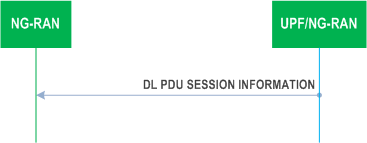
The purpose of the Transfer of DL PDU Session Information procedure is to send control information elements related to the PDU Session from UPF to NG-RAN.
In the case of uplink and downlink data forwarding the DL PDU Session Information procedure shall also be used to send control information elements related to the PDU Session from NG-RAN node to UPF, or from UPF to NG-RAN node, or between NG-RAN nodes.
A PDU Session user plane instance making use of the Transfer of DL PDU Session Information procedure is associated to a single PDU Session. The Transfer of DL PDU Session Information procedure may be invoked whenever packets for that particular PDU Session need to be transferred across the related interface instance.
The DL PDU SESSION INFORMATION frame includes a QoS Flow Identifier (QFI) field associated with the transferred packet. The NG-RAN shall use the received QFI to determine the QoS flow and QoS profile which are associated with the received packet.
The DL PDU SESSION INFORMATION frame shall include the Reflective QoS Indicator (RQI) field to indicate whether user plane Reflective QoS shall be activated or not. The NG-RAN shall, if RQA has been configured for the involved QoS flow as specified in TS 38.413, take the RQI into account as specified in TS 37.324.
The DL PDU SESSION INFORMATION frame may also include a Paging Policy Indicator (PPI) field associated with the transferred packet. The NG-RAN shall use the received PPI to determine the paging policy differentiation which is associated with the received packet as described in TS 23.501.
The DL PDU SESSION INFORMATION frame may also include a QoS Monitoring Packet (QMP) field and a DL sending time stamp field. The NG-RAN shall, if QoS monitoring has been configured for the included QFI field, perform delay measurement and QoS monitoring, as specified in TS 23.501.
The DL PDU SESSION INFORMATION frame may also include a DL QFI Sequence Number field associated with the transferred packet. The NG-RAN shall, if the QoS flow has been configured eligible for redundant transport bearer in TS 38.413, use the received DL QFI Sequence Number field to determine and eliminate duplicated packets for a given QoS flow as specified in TS 23.501.
The DL PDU SESSION INFORMATION frame may also include a DL MBS QFI Sequence Number field associated with the transferred packet. The NG-RAN shall use the received DL MBS QFI Sequence Number field to determine the PDCP count that should be used when transferring the packet over the radio as specified in TS 38.300.
When needed, the NG-RAN shall propagate the DL PDU Session Information to a peer NG-RAN.
5.4.1.2 Unsuccessful operation p. 9
Void.
5.4.2 Transfer of UL PDU Session Information p. 9
5.4.2.1 Successful operation p. 9
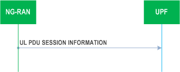
The purpose of the Transfer of UL PDU Session Information procedure is to send control information elements related to the PDU Session from NG-RAN to UPF.
An UL PDU Session user plane instance making use of the Transfer of UL PDU Session Information procedure is associated to a single PDU Session. The Transfer of UL PDU Session Information procedure may be invoked whenever packets for that particular PDU Session need to be transferred across the related interface instance.
The UL PDU SESSION INFORMATION frame includes a QoS Flow Identifier (QFI) field associated with the transferred packet.
If QoS monitoring has been requested for the included QFI field, the UL PDU SESSION INFORMATION frame may include a QoS Monitoring Packet (QMP) field, a DL Sending Time Stamp Repeated field, a DL Receiving Time Stamp field, a UL Sending Time Stamp field, and/or Delay Result for UL or DL. If QoS monitoring with N3/N9 delay reporting has been requested for the included QFI field, the I-UPF may include in the UL PDU SESSION INFORMATION frame a N3/N9 Delay Ind. field, a N3/N9 Delay Result field and delay result for UL and DL if received from the RAN. The UPF shall, if supported, use this information to calculate UL, DL, or RTT delay as specified in TS 23.501.
The UL PDU SESSION INFORMATION frame may also include a UL QFI Sequence Number field associated with the transferred packet. The UPF shall, if the QoS flow has been configured eligible for redundant transport bearer in TS 38.413, use the received UL QFI Sequence Number field to determine and eliminate duplicated packets for a given QoS flow as specified in TS 23.501.
If the ECN Marking or Congestion Information Reporting Status is active for a QoS flow indicated by the QFI field, the UL PDU SESSION INFORMATION frame should include an UL Congestion Information field and/or a DL Congestion Information field. The UPF shall, if supported, use this information to perform ECN marking at UPF or information exposure as specified in TS 23.501.
5.4.2.2 Unsuccessful operation p. 9
Void.
5.5 Elements for the PDU Session user plane protocol p. 10
5.5.1 General p. 10
In the present document the structure of frames are specified by using Figures similar to Figure 5.5.1-1.
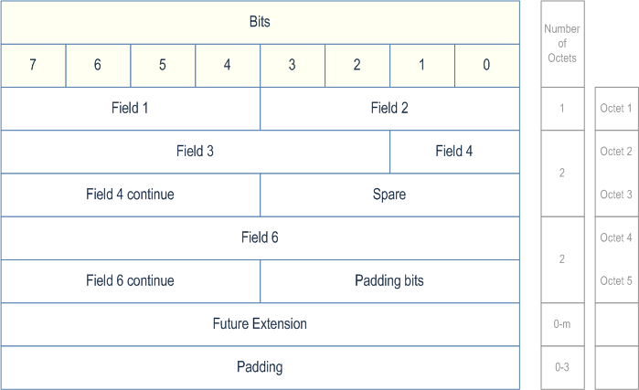
Unless otherwise indicated, fields which consist of multiple bits within an octet have the most significant bit located at the higher bit position (indicated above frame in Figure 5.5.1-1). In addition, if a field spans several octets, most significant bits are located in lower numbered octets (right of frame in Figure 5.5.1-1).
Unless otherwise indicated, fields which consist of multiple bits within an octet have the most significant bit located at the higher bit position (indicated above frame in Figure 5.5.1-1). In addition, if a field spans several octets, most significant bits are located in lower numbered octets (right of frame in Figure 5.5.1-1).
On the NG interface, the frame is transmitted starting from the lowest numbered octet. Within each octet, the bits are sent according to decreasing bit position (bit position 7 first).
Spare bits should be set to "0" by the sender and should not be checked by the receiver.
The header part of the frame is always an integer number of octets. The payload part is octet aligned (by adding 'Padding Bits' when needed).
The receiver should be able to remove an additional Future Extension field that may be present.
See description of Future Extension field in clause A.1.
Padding octets may be added at the end of the frame, see Padding in clause 5.5.3.5.
5.5.2 Frame format for the PDU Session user plane protocol p. 10
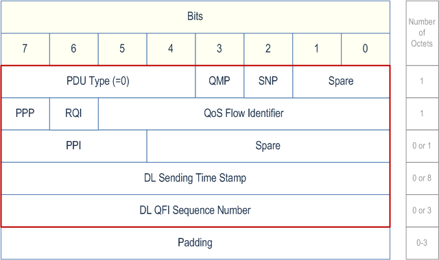
5.5.2.1 DL PDU SESSION INFORMATION (PDU Type 0) p. 10
This frame format is defined to allow the NG-RAN to receive some control information elements which are associated with the transfer of a packet over the interface.
The following shows the respective DL PDU SESSION INFORMATION frame.
5.5.2.2 UL PDU SESSION INFORMATION (PDU Type 1) p. 11
This frame format is defined to allow the UPF to receive some control information elements which are associated with the transfer of a packet over the interface.
The following shows the respective UL PDU SESSION INFORMATION frame.
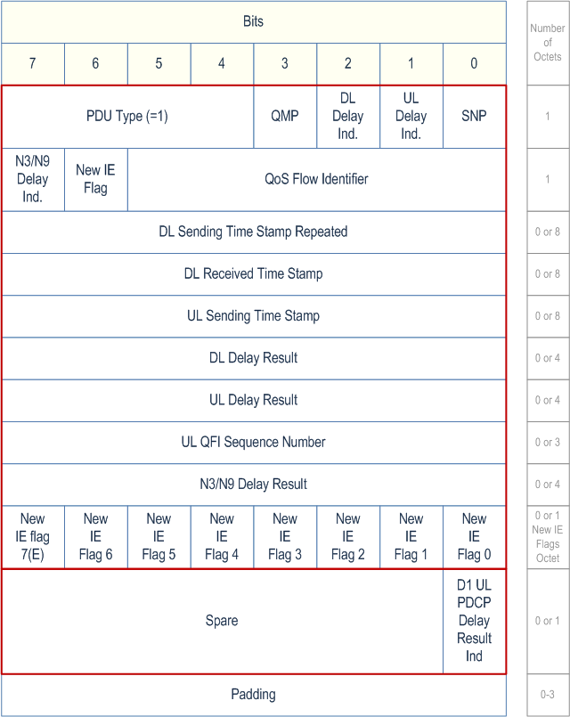
The New IE Flag in bit 6 of 2nd octet in UL PDU SESSION INFORMATION (PDU Type 1) indicates if the first octet of New IE Flags Octet is present or not.
Bit 0 of New IE Flags Octet in UL PDU SESSION INFORMATION (PDU Type 1) indicates if the D1 UL PDCP Delay Result Ind is present (1) or not (0)
Bit 0 of New IE Flags Octet in UL PDU SESSION INFORMATION (PDU Type 1) indicates if the D1 UL PDCP Delay Result Ind is present (1) or not (0).
Bit 1 of New IE Flags Octet in UL PDU SESSION INFORMATION (PDU Type 1) indicates if the UL Congestion Information is present (1) or not (0).
Bit 2 of New IE Flags Octet in UL PDU SESSION INFORMATION (PDU Type 1) indicates if the DL Congestion Information is present (1) or not (0).
5.5.3 Coding of information elements in frames p. 12
5.5.3.1 PDU Type p. 12
Description:
The PDU Type indicates the structure of the PDU session UP frame. The field takes the value of the PDU Type it identifies; i.e. "0" for PDU Type 0. The PDU type is in bit 4 to bit 7 in the first octet of the frame.
Value range:
{0= DL PDU SESSION INFORMATION, 1=UL PDU SESSION INFORMATION, 2-15=reserved for future PDU type extensions}.
Field length:
4 bits.
5.5.3.2 Spare p. 12
Description:
The spare field is set to "0" by the sender and should not be interpreted by the receiver. This field is reserved for later versions.
Value range:
(0-2n-1).
Field length:
n bits.
5.5.3.3 QoS Flow Identifier (QFI) p. 12
Description:
When present this parameter indicates the QoS Flow Identifier of the QoS flow to which the transferred packet belongs.
Value range:
{0..26-1}.
Field length:
6 bits.
5.5.3.4 Reflective QoS Indicator (RQI) p. 12
Description:
This parameter indicates activation of the reflective QoS towards the UE for the transferred packet as described in clause 5.4.1.1. It is used only in the downlink direction. If RQA (Reflective QoS Activation) has not been configured for the involved QoS flow, the RQI shall be ignored by the NG-RAN node.
Value range:
{0= Reflective QoS activation not triggered, 1= Reflective QoS activation triggered}.
Field length:
1 bit.
5.5.3.5 Padding p. 13
Description:
The padding is included at the end of the frame to ensure that the PDU Session user plane protocol PDU length (including padding and the future extension) is (n*4- 2) octets, where n is a positive integer. If there is any future extension, the padding should be added after the future extensions.
Field length:
0-3 octets.
5.5.3.6 Paging Policy Presence (PPP) p. 13
Description:
This parameter indicates the presence of the Paging Policy Indicator (PPI).
Value range:
{0= Paging Policy Indicator not present, 1= Paging Policy Indicator present}.
Field length:
1 bit.
5.5.3.7 Paging Policy Indicator (PPI) p. 13
Description:
When present, the Paging Policy Indicator is used for paging policy differentiation (see details in TS 23.501). This field applies to PDU sessions of IP type.
Value range:
{0..23-1}.
Field length:
3 bits.
5.5.3.8 QoS Monitoring Packet (QMP) |R16| p. 13
Description:
This parameter indicates that the transferred packet is used for QoS monitoring as described in clause 5.4.1.1 and clause 5.4.2.1. This parameter also indicates the presence of the DL Sending Time Stamp in the DL PDU Session Information frame and the presence of the DL Sending Time Stamp Repeated, the DL Receiving Time Stamp, the UL Sending Time Stamp in the UL PDU Session Information frame. If QoS monitoring has not been configured for the involved QoS flow, the QMP shall be ignored by the NG-RAN node.
Value range:
{0= not used for QoS monitoring, 1= used for QoS monitoring}.
Field length:
1 bit.
5.5.3.9 DL Sending Time Stamp |R16| p. 13
Description:
This field indicates the time when the UPF sends the DL PDU Session Information frame with the QMP field set to 1. It is used only in the downlink direction and encoded in the same format as the 64-bit timestamp format as defined in Section 6 of RFC 5905.
Value range:
{0..264-1}.
Field length:
8 octets.
5.5.3.10 DL Sending Time Stamp Repeated |R16| p. 13
Description:
This field indicates the value of the DL Sending Time Stamp field that the NG-RAN has received in the DL PDU Session Information frame with the QMP field set to 1 for the involved QoS flow. It is used only in the uplink direction and encoded in the same format as the 64-bit timestamp format as defined in Section 6 of RFC 5905. The UPF shall, if supported, use this information to calculate DL or RTT delay between the NG-RAN and the UPF as specified in TS 23.501.
Value range:
{0..264-1}.
Field length:
8 octets.
5.5.3.11 DL Received Time Stamp |R16| p. 14
Description:
This field indicates the time when the NG-RAN node receives the DL PDU Session Information frame with the QMP field set to 1 for the involved QoS flow. It is used only in the uplink direction and encoded in the same format as the 64-bit timestamp format as defined in Section 6 of RFC 5905. The UPF shall, if supported, use this information to calculate DL or RTT delay between the NG-RAN and the UPF as specified in TS 23.501.
Value range:
{0..264-1}.
Field length:
8 octets.
5.5.3.12 UL Sending Time Stamp |R16| p. 14
Description:
This field indicates the time when the NG-RAN node sends this UL PDU Session Information frame. It is used only in the uplink direction and encoded in the same format as the 64-bit timestamp format as defined in Section 6 of RFC 5905. The UPF shall, if supported, use this information to calculate UL or RTT delay between the NG-RAN and the UPF as specified in TS 23.501.
Value range:
{0..264-1}.
Field length:
8 octets.
5.5.3.13 DL Delay Ind. |R16| p. 14
Description:
This parameter indicates the presence of DL Delay Result.
Value range:
{0= DL Delay Result not present, 1= DL Delay Result present}.
Field length:
1 bit.
5.5.3.14 DL Delay Result |R16| p. 14
Description:
This field indicates the downlink delay measurement result which is the sum of the delay incurred in NG-RAN (including the delay at gNB-CU-UP, on F1-U and on gNB-DU) and the delay over Uu interface in milliseconds for the involved QoS flow. It is used only in the uplink direction and encoded as an Unsigned32 binary integer value. The UPF shall, if supported, use this information to calculate DL or RTT delay as specified in TS 23.501.
Value range:
{0..232-1}.
Field length:
4 octets.
5.5.3.15 UL Delay Ind. |R16| p. 14
Description:
This parameter indicates the presence of UL Delay Result.
Value range:
{0= UL Delay Result not present, 1= UL Delay Result present}.
Field length:
1 bit.
5.5.3.16 UL Delay Result |R16| p. 14
Description:
This field indicates the uplink delay measurement result which is the sum of the delay incurred in NG-RAN (including the delay at gNB-CU-UP, on F1-U and on gNB-DU), the delay over Uu interface and the delay in the UE in milliseconds for the involved QoS flow. It is used only in the uplink direction and encoded as an Unsigned32 binary integer value. The UPF shall, if supported, use this information to calculate UL or RTT delay as specified in TS 23.501.
Value range:
{0..232-1}.
Field length:
4 octets.
5.5.3.17 Sequence Number Presence (SNP) |R16| p. 15
Description:
This parameter indicates the presence of the DL QFI Sequence Number in the DL PDU Session Information frame or the presence of the UL QFI Sequence Number in the UL PDU Session Information frame.
Value range:
{0= DL/UL QFI Sequence Number not present, 1= DL/UL QFI Sequence Number present}.
Field length:
1 bit.
5.5.3.18 DL QFI Sequence Number |R16| p. 15
Description:
This parameter indicates the sequence number as assigned by the UPF associated with a given QoS Flow.
Value range:
{0..224-1}.
Field length:
3 octets.
5.5.3.19 UL QFI Sequence Number |R16| p. 15
Description:
This parameter indicates the sequence number as assigned by the NG-RAN node associated with a given QoS flow.
Value range:
{0..224-1}.
Field length:
3 octets.
5.5.3.20 N3/N9 Delay Ind. |R16| p. 15
Description:
This parameter indicates the presence of N3/N9 Delay Result.
Value range:
{0= N3/N9 Delay Result not present, 1= N3/N9 Delay Result present}.
Field length:
1 bit.
5.5.3.21 N3/N9 Delay Result |R16| p. 15
Description:
This field indicates the accumulated N3 and N9 packet delay as specified in TS 23.501, and is reported by the I-UPF. The reported value is expressed in milliseconds and encoded as an Unsigned32 binary integer value.
Value range:
{0..232-1}.
Field length:
4 octets.
5.5.3.22 D1 UL PDCP Delay Result Ind |R16| p. 15
Description:
This parameter indicates if the UL Delay Result includes or not includes the D1 measurement (UL PDCP Packet Average Delay). This parameter shall be ignored if the UL Delay Ind is set to "0".
Value range:
{0= D1 UL PDCP Packet Average Delay measurement is not included, 1= D1 UL PDCP Packet Average Delay measurement is included}.
Field length:
1 bit.
5.5.3.23 MBS Sequence Number Presence (MSNP) |R17| p. 15
Description:
This parameter indicates the presence of the DL MBS QFI Sequence Number in the DL PDU Session Information frame.
Value range:
{0= DL MBS QFI Sequence Number not present, 1= DL MBS QFI Sequence Number present}.
Field length:
1 bit.
5.5.3.24 DL MBS QFI Sequence Number |R17| p. 16
Description:
This parameter indicates the sequence number as assigned by the MB-UPF associated with a given MBS QoS Flow.
Value range:
{0..232-1}.
Field length:
4 octets.
5.5.3.25 DL Congestion Information |R18| p. 16
Description:
For the cases of ECN marking at UPF request, this field indicates the percentage of DL IP packets up to two decimal points that should be ECN marked for a QoS flow.
For the case of congestion information request, this field should be interpreted as a percentage of congestion level in DL up to two decimal points for a QoS flow.
As an example, value 9574 corresponds to a percentage of 95.74%.
Value range:
{0..10000}.
Field length:
2 octets.
5.5.3.26 UL Congestion Information |R18| p. 16
Description:
For the cases of ECN marking at UPF request, this field indicates the percentage of UL IP packets up to two decimal points that should be ECN marked for a QoS flow.
For the case of congestion information request, this field should be interpreted as a percentage of congestion level in UL up to two decimal points for a QoS Flow.
As an example, value 9574 corresponds to a percentage of 95.74%.
Value range:
{0..10000}.
Field length:
2 octets.
5.5.4 Timers p. 16
Void.
5.6 Handling of unknown, unforeseen and erroneous protocol data p. 16
Void.
6 PDU Set Information user plane protocol |R18| p. 16
6.1 General p. 16
The PDU Set Information UP layer uses the services of the Transport Network Layer in order to send its packets over the interface.
6.2 PDU Set Information user plane protocol layer services p. 16
The following functions are provided by the PDU Set Information User Plane protocol:
- Provision of PDU Set Information elements associated with a QoS flow.
- Provision of Indication of End of Data Burst for a QoS flow.
6.3 Services expected from the Transport Network Layer p. 17
The PDU Set Information UP layer expects the following services from the Transport Network Layer:
- Transfer of PDU Set Information User Plane PDUs.
6.4 Elementary procedures p. 17
6.4.1 Transfer of DL PDU Set Information p. 17
6.4.1.1 Successful operation p. 17
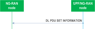
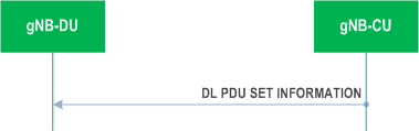
The purpose of the Transfer of DL PDU Set Information procedure is to send PDU Set information and indication of End of Data Burst related to a QoS flow from UPF to NG-RAN node or between NG-RAN nodes, or from gNB-CU to gNB-DU.
The DL PDU SET INFORMATION frame includes a QoS Flow Identifier (QFI) field associated with the transferred packet. The NG-RAN shall use the received QFI to determine the QoS flow and QoS profile which are associated with the received packet.
The DL PDU SET INFORMATION frame includes PDU Set Sequence Number, PDU Sequence Number within a PDU Set, PDU Set Importance, End of Data Burst and End PDU of the PDU Set as specified in TS 23.501.
The DL PDU SET INFORMATION frame may include PDU Set Size as specified in TS 23.501.
6.4.1.2 Unsuccessful operation p. 17
Void.
6.5 Elements for the PDU Set Information user plane protocol p. 18
6.5.1 General p. 18
The structure of frames is specified as in the clause 5.5.1.
6.5.2 Frame format for the PDU Set Information user plane protocol p. 18
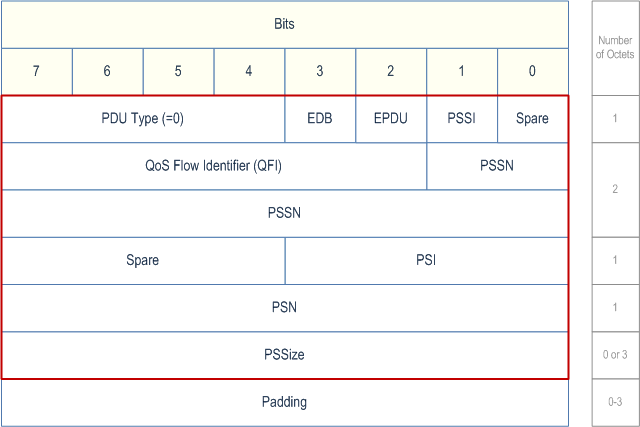
6.5.2.1 DL PDU SET INFORMATION (PDU Type 0) p. 18
This frame format is defined to allow the NG-RAN node or gNB-DU to receive PDU Set Information and indication of End of Data Burst of a QoS flow.
The following shows the respective DL PDU SET INFORMATION frame.
6.5.3 Coding of information elements in frames p. 18
6.5.3.1 PDU Type p. 18
Description:
The PDU Type indicates the structure of the PDU Set UP frame. The field takes the value of the PDU Type it identifies; i.e. "0" for PDU Type 0. The PDU type is in bit 4 to bit 7 in the first octet of the frame.
Value range:
{0= DL PDU SET INFORMATION, 1-15=reserved for future PDU type extensions}.
Field length:
4 bits.
6.5.3.2 Spare p. 18
Description:
The spare field is set to "0" by the sender and should not be interpreted by the receiver. This field is reserved for later versions.
Value range:
(0-2n-1).
Field Length:
n bits.
6.5.3.3 QoS Flow Identifier (QFI) p. 19
Description:
When present this parameter indicates the QoS Flow Identifier of the QoS flow to which the transferred packet belongs.
Value range:
{0..26-1}.
Field length:
6 bits.
6.5.3.5 PSSI (PDU Set Size Indicator) p. 19
Description:
This parameter indicates the presence of PDU Set Size (PSSize).
Value range:
{0= PSSize not present, 1= PSSize present}.
Field length:
1 bit.
6.5.3.6 Void
6.5.3.7 End PDU of the PDU Set (EPDU) p. 19
Description:
This parameter indicates whether the current PDU is the last PDU of the PDU set.
Value range:
{0= all other PDUs of the PDU Set, 1= last PDU of the PDU set}.
Field length:
1 bit.
6.5.3.8 End of Data Burst (EDB) p. 19
Description:
This parameter indicates the end of a Data Burst.
Value range:
{0 =all other PDUs, 1= the last PDU of a data burst}.
Field length:
1 bit.
6.5.3.9 PDU Set Importance (PSI) p. 19
Description:
This parameter indicates the importance of the current PDU Set compared to other PDU Sets within the same QoS flow. Lower values shall indicate a higher importance with the exception that value "0" means sender cannot define importance. PDU Set with the highest importance PDU Set is indicated by 1 and the lowest importance PDU Set is indicated by 15.
Value range:
{0..24-1}.
Field length:
4 bits.
6.5.3.10 PDU Set Sequence Number (PSSN) p. 19
Description:
This parameter indicates the sequence number of the PDU Set to which the current PDU belongs acting as an identifier for the PDU Set.
Value range:
{0..210-1}.
Field length:
10 bits.
6.5.3.11 PDU Sequence Number within a PDU Set (PSN) p. 19
Description:
This parameter indicates the sequence number of the current PDU within the PDU Set. The PSN shall be set to 0 for the first PDU in the PDU Set and incremented monotonically for every PDU in the PDU set in order of transmission from the sender.
Value range:
{0..28-1}.
Field length:
1 octet.
6.5.3.12 PDU Set Size (PSSize) p. 20
Description:
This parameter indicates the total size of all PDUs in bytes of the PDU Set to which the current PDU belongs.
Value range:
{0..224-1}.
Field length:
3 octets.
6.5.4 Timers p. 20
Void.
6.6 Handling of unknown, unforeseen and erroneous protocol data p. 20
Void.
A Example of using Future Extension Field p. 21
A.1 Example of using Future Extension field p. 21
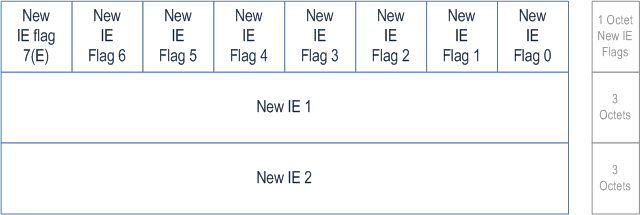
In the Example of the future Extension Field, New IE flag 0 indicates if the New IE 1 is present or not. New IE flag 1 indicates if the new IE 2 is present or not.
A.1.1 New IE Flags p. 21
Description:
The New IE Flags IE is only present if at least one new IE is present. The New IE Flags IE contains flags indicating which new IEs that are present following the New IE Flags IE. The last bit position of the New IE Flags IE is used as the Extension Flag to allow the extension of the New IE Flags IE in the future. Extension octets of the New IE Flags IE shall follow directly after the first octet of the New IE Flags IE. When an extension octet of the New IE Flags IE is present, then all previous extension octets of the New IE Flags IE and the New IE Flags IE shall also be present, even if they have all their flag bits indicating no presence of their respective new IEs.
$ Change history p. 22
![]()
![]()