TS 38.201
5G New Radio —
Physical Layer General Description
V18.0.0 (PDF)
2023/09 15 p.
V17.0.0
2021/12 15 p.
V16.0.0
2019/12 15 p.
V15.0.0
2017/12 14 p.
- Rapporteur:
- Mr. Nagata, Satoshi
NTT DOCOMO INC.
Content for TS 38.201 Word version: 18.0.0
1 Scope
2 References
3 Definitions of terms, symbols and abbreviations
4 General description of layer 1
4.1 Relation to other layers
4.2 General description of layer 1
5 Document structure of physical layer specification
A Preferred mathematical notations
$ Change History
1 Scope p. 5
The present document provides a general description of the physical layer of NR radio interface. The present document also describes the document structure of the 3GPP physical layer specifications, i.e. TS 38.200 series.
2 References p. 5
The following documents contain provisions which, through reference in this text, constitute provisions of the present document.
[1]
TR 21.905: "Vocabulary for 3GPP Specifications"
[2]
TS 38.202: "NR; Services provided by the physical layer"
[3]
TS 38.211: "NR; Physical channels and modulation"
[4]
TS 38.212: "NR; Multiplexing and channel coding"
[5]
TS 38.213: "NR; Physical layer procedures for control"
[6]
TS 38.214: "NR; Physical layer procedures for data"
[7]
TS 38.215: "NR; Physical layer measurements"
3 Definitions of terms, symbols and abbreviations p. 5
3.1 Terms p. 5
For the purposes of the present document, the terms and definitions given in TR 21.905 and the following apply. A term defined in the present document takes precedence over the definition of the same term, if any, in TR 21.905.
Void
3.2 Symbols p. 5
For the purposes of the present document, the following symbols apply:
Void
3.3 Abbreviations p. 5
For the purposes of the present document, the abbreviations given in TR 21.905 and the following apply. An abbreviation defined in the present document takes precedence over the definition of the same abbreviation, if any, in TR 21.905.
BPSK
Binary Phase Shift Keying
CP
Cyclic Prefix
DFT-s-OFDM
Discrete Fourier Transform-spread-Orthogonal Frequency Division Multiplexing
DU
Distributed Unit
E-UTRA
Evolved Universal Terrestrial Radio Access
FDD
Frequency Division Duplex
FEC
Forward Error Correction
HARQ
Hybrid Automatic Repeat Request
IAB
Integrated Access and Backhaul
LDPC
Low Density Parity Check
MAC
Medium Access Control
MIMO
Multiple Input Multiple Output
MT
Mobile Termination
NCR
Network-Controlled Repeater
OFDM
Orthogonal Frequency Division Multiplexing
PBCH
Physical Broadcast Channel
PDCCH
Physical Downlink Control Channel
PDSCH
Physical Downlink Shared Channel
PRACH
Physical Random Access Channel
PSBCH
Physical Sidelink Broadcast Channel
PSCCH
Physical Sidelink Control Channel
PSFCH
Physical Sidelink Feedback Channel
PSSCH
Physical Sidelink Shared Channel
PUCCH
Physical Uplink Control Channel
PUSCH
Physical Uplink Shared Channel
QAM
Quadrature Amplitude Modulation
QPSK
Quadrature Phase Shift Keying
RLC
Radio Link Control
RRC
Radio Resource Control
SAP
Service Access Point
SRS
Sounding Reference Signal
TDD
Time Division Duplex
UE
User Equipment
4 General description of layer 1 p. 6
4.1 Relation to other layers p. 6
4.1.1 General protocol architecture p. 6
The radio interface described in this specification covers the interface between the User Equipment (UE) and gNB, between gNBs, between IAB-node DU and IAB-node MT/UE, between gNB and NCR-MT, and between UEs. The radio interface is composed of the Layer 1, 2 and 3. The TS 38.200 series describes the Layer 1 (Physical Layer) specifications. Layers 2 and 3 are described in the 38.300 series.

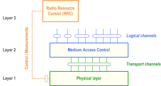
Figure 1 shows the NR radio interface protocol architecture around the physical layer (Layer 1). The physical layer interfaces the Medium Access Control (MAC) sub-layer of Layer 2 and the Radio Resource Control (RRC) Layer of Layer 3. The circles between different layer/sub-layers indicate Service Access Points (SAPs). The physical layer offers a transport channel to MAC. The transport channel is characterized by how the information is transferred over the radio interface. MAC offers different logical channels to the Radio Link Control (RLC) sub-layer of Layer 2. A logical channel is characterized by the type of information transferred.
4.1.2 Service provided to higher layers p. 7
The physical layer offers data transport services to higher layers. The access to these services is through the use of a transport channel via the MAC sub-layer. Details are specified in TS 38.202.
4.2 General description of layer 1 p. 7
4.2.1 Multiple access p. 7
The multiple access scheme for the NR physical layer is based on Orthogonal Frequency Division Multiplexing (OFDM) with a cyclic prefix (CP). For uplink, Discrete Fourier Transform-spread-OFDM (DFT-s-OFDM) with a CP is also supported. To support transmission in paired and unpaired spectrum, both Frequency Division Duplex (FDD) and Time Division Duplex (TDD) are enabled.
The Layer 1 is defined in a bandwidth agnostic way based on resource blocks, allowing the NR Layer 1 to adapt to various spectrum allocations. A resource block spans 12 sub-carriers with a given sub-carrier spacing.
The radio frame has a duration of 10ms and consists of 10 sub-frames with a sub-frame duration of 1ms. A sub-frame is formed by one or multiple adjacent slots, each having 14 adjacent symbols. Further details on the frame structure are specified in TS 38.202.
4.2.2 Physical channels and modulation p. 7
The physical channels defined in the downlink are:
- the Physical Downlink Shared Channel (PDSCH),
- the Physical Downlink Control Channel (PDCCH),
- the Physical Broadcast Channel (PBCH),
- the Physical Random Access Channel (PRACH),
- the Physical Uplink Shared Channel (PUSCH),
- and the Physical Uplink Control Channel (PUCCH).
- the Physical Sidelink Broadcast Channel (PSBCH),
- the Physical Sidelink Control Channel (PSCCH),
- the Physical Sidelink Feedback Channel (PSFCH),
- and the Physical Sidelink Shared Channel (PSSCH).
- in the downlink, QPSK, 16QAM, 64QAM, 256QAM, and 1024QAM,
- in the uplink, QPSK, 16QAM, 64QAM and 256QAM for OFDM with a CP and ϖ/2-BPSK, QPSK, 16QAM, 64QAM and 256QAM for DFT-s-OFDM with a CP.
4.2.3 Channel coding p. 8
The channel coding scheme for transport blocks is quasi-cyclic LDPC codes with 2 base graphs and 8 sets of parity check matrices for each base graph, respectively. One base graph is used for code blocks larger than certain sizes or with initial transmission code rate higher than thresholds; otherwise, the other base graph is used. Before the LDPC coding, for large transport blocks, the transport block is segmented into multiple code blocks with equal size. The channel coding scheme for PBCH and control information is Polar coding based on nested sequences. Puncturing, shortening and repetition are used for rate matching. Further details of channel coding schemes are specified in TS 38.212.
4.2.4 Physical layer procedures p. 8
There are several Physical layer procedures involved. Such procedures covered by the physical layer are;
- Cell search
- Power control
- Uplink synchronisation and Uplink timing control
- Random access related procedures
- HARQ related procedures
- Beam management and CSI related procedures
- Sidelink related procedures
- Channel access procedures
4.2.5 Physical layer measurements p. 8
Radio characteristics are measured by the UE and the network and reported to higher layers. These include, e.g. measurements for intra- and inter-frequency handover, inter RAT handover, timing measurements, and measurements for RRM.
Measurements for inter-RAT handover are defined in support of handover to E-UTRA.
5 Document structure of physical layer specification p. 8
5.1 Overview p. 8
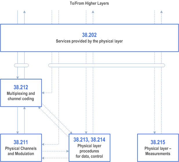
The physical layer specification consists of a general document (TS 38.201), and seven documents (TS 38.202, TS 38.211 through TS 38.215, and TS 37.213). The relation between the physical layer specifications in the context of the higher layers is shown in Figure 2.

5.2 TS 38.201: Physical layer; General description p. 9
The scope is to describe:
- The contents of the Layer 1 documents (TS 38.200 series);
- Where to find information;
5.3 TS 38.202: Physical layer services provided by the physical layer p. 9
The scope is to describe services provided by the physical layer, and to specify:
- Services and functions of the physical layer;
- Model of physical layer of the UE;
- Parallel transmission of simultaneous physical channels and SRS;
- Measurements provided by the physical layer.
5.4 TS 38.211: Physical channels and modulation p. 9
The scope is to establish the characteristics of the Layer-1 physical channels, generation of physical layer signals and modulation, and to specify:
- Definition of the uplink, downlink and sidelink physical channels;
- Frame structure and physical resources;
- Modulation mapping (BPSK, QPSK, etc);
- OFDM signal generation;
- Scrambling, modulation and upconversion;
- Layer mapping and precoding;
- Physical shared channel in uplink, downlink and sidelink;
- Reference signal in uplink, downlink and sidelink;
- Physical random access channel;
- Primary and secondary synchronization signals.
5.5 TS 38.212: Multiplexing and channel coding p. 10
The scope is to describe the transport channel and control channel data processing, including multiplexing, channel coding and interleaving, and to specify:
- Channel coding schemes;
- Rate matching;
- Uplink transport channels and control information;
- Downlink transport channels and control information;
- Sidelink transport channels and control information.
5.6 TS 38.213: Physical layer procedures for control p. 10
The scope is to establish the characteristics of the physical layer procedures for control, and to specify:
- Synchronization procedures;
- Uplink power control;
- Random access procedure;
- UE procedure for reporting control information;
- UE procedure for receiving control information.
5.7 TS 38.214: Physical layer procedures for data p. 10
The scope is to establish the characteristics of the physical layer procedures for data, and to specify:
- Power control;
- Physical downlink shared channel related procedures;
- Physical uplink shared channel related procedure;
- Physical sidelink shared channel related procedure.
5.8 TS 38.215: Physical layer measurements p. 10
The scope is to establish the characteristics of the physical layer measurements, and to specify:
- Control of UE/NG-RAN measurements;
- Measurement capabilities for NR.
5.9 TS 37.213: Physical layer procedures for shared spectrum channel access p. 10
The scope is to establish the characteristics of the physical layer procedures for shared spectrum channel, and to specify:
- Downlink channel access procedures;
- Uplink channel access procedures;
- Sidelink channel access procedures.
A Preferred mathematical notations p. 12
The following table contains the preferred mathematical notations used in L1 documentation.
| item | notation |
|---|---|
| multiply product | cross sign, e.g.
a×b
|
| matrix product | dot sign, e.g.
a⋅b
|
| scalar product (product of a matrix by a scalar) | dot sign, scalar should precede matrix e.g.

|
| matrix dimensioning |
number of rows × number of column, e.g.:
R×C
|
| Kronecker product | a⊗b |
| bracketing of sets (all elements of same type, not ordered elements) |
curly brackets {}, e.g.

|
| bracketing of lists (all elements not necessary of same type, ordered elements) |
round brackets (), e.g.
(A, u, x)
|
| bracketing of sequences (all elements of same type, ordered elements) |
angle brackets, e.g.

|
| bracketing of function argument |
round brackets, e.g.
f(x)
|
| bracketing of array index |
square brackets, e.g.
a[x]
|
| bracketing of matrix or vector |
square brackets [], e.g.

|
| Separation of indexes |
use a comma: e.g.
Ni,j
|
| use of italic for symbols | a symbol should be either in italic or in normal font, but mixing up should be avoided. |
| bracketing of arithmetic expression to force precedence of operations |
round brackets : e.g.

|
| necessity of bracketing arithmetic expressions | When only + and × bracketing is not necessary. When the mod operator is used explicit bracketing of mod operands and possibly result should be done. |
| number type | in a context of non negative integer numbers, some notes should stress when a number is signed, or possibly fractional. |
| binary xor and and | respectively use + or ⋅. If no "mod 2" is explicitly in the expression some text should stress that the operation is modulo 2. |
| matrix or vector transpose | vT |
| 1x1 matrices | implicitly cast to its unique element. |
| vector dot product | uT⋅v for column vectors, and u⋅vT for line vectors |
| complex conjugate | v* |
| matrix or vector Hermitian transpose | vH |
| real part and imaginary part of complex numbers | Re(x) and Im(x) |
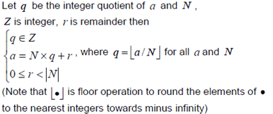
| Modulo operation (including negative value) r ≡ a mod N |

|