Content for TS 37.114 Word version: 18.1.0
1 Scope p. 8
The present document covers the assessment of UTRA TDD, UTRA FDD, E-UTRA, NR and Multi-Standard Radio (MSR) Active Antenna Systems Base Stations in respect of Electromagnetic Compatibility (EMC).
The present document specifies the applicable test conditions, performance assessment and performance criteria for base stations in the following categories:
- Active Antenna System Base Station for UTRA TDD, UTRA FDD, E-UTRA, NR and MSR meeting the conducted requirements of TS 37.105, with conformance demonstrated by compliance to TS 37.145-1,
- Active Antenna System Base Station for UTRA FDD, E-UTRA, NR and MSR meeting the OTA requirements of 3TS 37.105, with conformance demonstrated by compliance to TS 37.145-2.
- Requirement, procedures and values of a hybrid AAS BS with TAB connectors for every transceiver unit at the transceiver array boundary (TAB), subject to conducted requirements,
- Requirements, procedures and values of an OTA AAS BS without TAB connectors and relying in the radiated interface, subject to radiated requirements.
2 References p. 8
The following documents contain provisions which, through reference in this text, constitute provisions of the present document.
- References are either specific (identified by date of publication, edition number, version number, etc.) or non-specific.
- For a specific reference, subsequent revisions do not apply.
- For a non-specific reference, the latest version applies. In the case of a reference to a 3GPP document (including a GSM document), a non-specific reference implicitly refers to the latest version of that document in the same Release as the present document.
[1]
TR 21.905: "Vocabulary for 3GPP Specifications".
[2]
TS 37.105: "Active Antenna System (AAS) Base Station (BS) transmission and reception".
[3]
TS 37.145-1: "Active Antenna System (AAS) Base Station (BS) conformance testing; Part 1: Conducted conformance testing".
[4]
TS 37.113: "E-UTRA, UTRA and GSM/EDGE; Multi-Standard Radio (MSR) Base Station (BS) Electromagnetic Compatibility (EMC)".
[5]
TS 25.113: "Base Station (BS) and repeater ElectroMagnetic Compatibility (EMC)".
[6]
TS 36.113: "Evolved Universal Terrestrial Radio Access (E-UTRA); Base Station (BS) and repeater ElectroMagnetic Compatibility (EMC)".
[7]
IEC 61000-6-1: 2016: "Electromagnetic compatibility (EMC) - Part 6-1: Generic standards - Immunity standard for residential, commercial and light-industrial environments".
[8]
IEC 61000-6-3: 2006/AMD1:2010: "Electromagnetic compatibility (EMC) - Part 6-3: Generic standards - Emission standard for residential, commercial and light-industrial environments".
[9] Void.
[10]
TS 37.145-2: "Active Antenna System (AAS) Base Station (BS) conformance testing; Part 2: radiated conformance testing".
[11]
IEC 61000-3-2: 2014: "Electromagnetic compatibility (EMC) - Part 3-2: Limits - Limits for harmonic current emissions (equipment input current ≤ 16 A per phase)".
[12]
IEC 61000-3-3: 2013: "Electromagnetic compatibility (EMC) - Part 3-3: Limits - Limitation of voltage changes, voltage fluctuations and flicker in public low-voltage supply systems, for equipment with rated current ≤ 16 A per phase and not subject to conditional connection".
[13]
IEC 61000-3-11: 2017 "Electromagnetic compatibility (EMC) - Part 3-11: Limits - Limitation of voltage changes, voltage fluctuations and flicker in public low-voltage supply systems - Equipment with rated current ≤ 75 A and subject to conditional connection".
[14]
IEC 61000-3-12: 2011: "Electromagnetic compatibility (EMC) - Part 3-12: Limits - Limits for harmonic currents produced by equipment connected to public low-voltage systems with input current >16 A and ≤ 75 A per phase".
[15]
IEC 61000-4-2: 2008: "Electromagnetic compatibility (EMC) - Part 4-2: Testing and measurement techniques - Electrostatic discharge immunity test".
[16]
IEC 61000-4-3: 2006+AMD1:2007+AMD2:2010: "Electromagnetic compatibility (EMC) - Part 4-3: Testing and measurement techniques - Radiated, radio-frequency, electromagnetic field immunity test".
[17]
IEC 61000-4-4: 2012: "Electromagnetic compatibility (EMC) - Part 4-4: Testing and measurement techniques - Electrical fast transient/burst immunity test".
[18]
IEC 61000-4-5: 2014+AMD1:2017: "Electromagnetic compatibility (EMC) - Part 4-5: Testing and measurement techniques - Surge immunity test".
[19]
IEC 61000-4-6: 2013: "Electromagnetic compatibility (EMC) - Part 4-6: Testing and measurement techniques - Immunity to conducted disturbances, induced by radio-frequency fields".
[20]
IEC 61000-4-11: 2004+AMD1:2017: "Electromagnetic compatibility (EMC) - Part 4-11: Testing and measurement techniques - Voltage dips, short interruptions and voltage variations immunity tests".
[21]
ETSI EN 301 489-1: "Electromagnetic compatibility and Radio spectrum Matters (ERM); ElectroMagnetic Compatibility (EMC) standard for radio equipment and services; Part 1: Common technical requirements".
[22] Void
[23] Void
[24]
ITU-R SM.329-10: "Unwanted emissions in the spurious domain".
[25]
ETSI EN 301 489-50, v2.1.0: "ElectroMagnetic Compatibility (EMC) standard for radio equipment and services; Part 50: Specific conditions for Cellular Communication Base Station (BS), repeater and ancillary equipment; Harmonised Standard covering the essential requirements of article 3.1(b) of Directive 2014/53/EU".
[26]
TS 25.102: "User Equipment (UE) radio transmission and reception (TDD)".
[27]
TS 25.101: "User Equipment (UE) radio transmission and reception (FDD)".
[28]
TS 36.101: "Evolved Universal Terrestrial Radio Access (E-UTRA); User Equipment (UE) radio transmission and reception".
[29]
CISPR 32: "Electromagnetic compatibility of multimedia equipment - Emission requirements".
[30]
TS 38.113: "NR; Base Station (BS) ElectroMagnetic Compatibility (EMC)".
[31]
TS 38.104: "NR; Base Station (BS) radio transmission and reception".
[32] Void
[33]
TS 37.104: "NR, E-UTRA, UTRA and GSM/EDGE; Multi-Standard Radio (MSR) Base Station (BS) radio transmission and reception".
[34]
TS 38.101-4: "NR; User Equipment (UE) radio transmission and reception; Part 4: Performance requirements".
[35]
IEC 61000-4-21: "Electromagnetic compatibility (EMC) - Part 4-21: Testing and measurement techniques - Reverberation chamber test methods".
3 Definitions, symbols and abbreviations p. 10
3.1 Definitions p. 10
For the purposes of the present document, the terms and definitions given in TR 21.905, TS 37.113 and the following apply. A term defined in the present document takes precedence over the definition of the same term, if any, in TR 21.905 or TS 37.113.
active antenna system base station:

 radiated interface boundary:
BS system which combines an antenna array with a transceiver unit array and a radio distribution network.
antenna array:
group of radiating elements characterized by the geometry and the properties of the array elements.
antenna port:
RF interface at the transceiver array boundary, specifically the TAB connectors.
BS type 1-H:
NR base station operating at FR1 with a requirement set consisting of conducted requirements defined at individual TAB connectors and OTA requirements defined at RIB.
BS type 1-O:
NR base station operating at FR1 with a requirement set consisting only of OTA requirements defined at the RIB.
hybrid AAS BS:
AAS BS which has both a conducted RF interface and a radiated RF interface in the far field and conforms to a hybrid requirements set.
MSR operation:
operation of AAS BS declared to be MSR in particular operating band(s), including any of UTRA, E-UTRA and/or NR operation as single RAT or multi-RAT based on TS 37.104 (see manufacturer's declaration D6.12 in TS 37.145-1 and/or D9.25 in TS 37.145-2).
NB-IoT In-band operation:
NB-IoT is operating in-band when it utilizes the resource block(s) within a normal E-UTRA carrier.
NB-IoT guard band operation:
NB-IoT is operating in guard band when it utilizes the unused resource block(s) within an E-UTRA carrier's guard-band.
NB-IoT standalone operation:
NB-IoT is operating standalone when it utilizes its own spectrum, for example the spectrum currently being used by GERAN systems as a replacement of one or more GSM carriers, as well as scattered spectrum for potential IoT deployment.
OTA AAS BS:
AAS BS which has ≥8 transceiver units for E-UTRA or MSR and ≥4 transceiver units for UTRA per cell and has a radiated RF interface only and conforms to the OTA requirements set.
OTA requirements set:
complete set of OTA requirements applied to an OTA AAS BS.
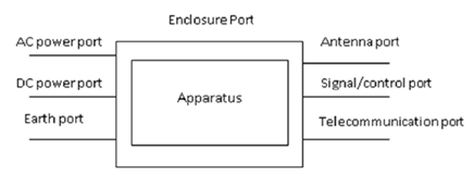
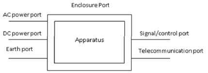
port:
particular interface of EUT used for EMC requirements testing purposes.
EXAMPLE 1: Examples of ports for hybrid AAS BS are as presented in Figure 3.1-1:

EXAMPLE 2: Examples of ports for OTA AAS BS (i.e. with no antenna ports) are as presented in Figure 3.1-2:

operating band specific radiated requirements reference where the radiated requirements apply.
radio distribution network:
linear passive network which distributes the RF power generated by the transceiver unit array to the antenna array, and/or distributes the radio signals collected by the antenna array to the transceiver unit array.
single RAT E-UTRA operation:
operation of AAS BS declared to be single RAT E-UTRA in the operating band (see manufacturer's declaration D6.12 in TS 37.145-1 and/or D9.25 in TS 37.145-2).
single RAT UTRA operation:
operation of AAS BS declared to be single RAT UTRA in the operating band (see manufacturer's declaration D6.12 in TS 37.145-1 and/or D9.25 in TS 37.145-2).
spatial exclusion zone:
range of angles where no tests of radiated immunity are made for OTA AAS BS (i.e. half sphere around the EUT's radiating direction).
TAB connector:
transceiver array boundary connector.
transceiver array boundary:
conducted interface between the transceiver unit array and the composite antenna.
transceiver unit:
active unit consisting of transmitter and/or receiver which transmits and/or receives radio signals, and which may include passive RF filters.
telecommunication port:
ports which are intended to be connected to telecommunication networks (e.g. public switched telecommunication networks, integrated services digital networks), local area networks (e.g. Ethernet, Token Ring) and similar networks.
3.2 Symbols p. 12
For the purposes of the present document, the following symbols apply:
BWChannel
Channel bandwidth
foffset
Frequency offset used for discovering narrowband response for receivers
FUL_high
The highest frequency of the uplink operating band
FUL_low
The lowest frequency of the uplink operating band
ΔfOOB
Maximum offset of the out-of-band boundary from the uplink operating band edge
ΔfRIexclusion
Maximum offset of the Radiated Immunity exclusion band from the uplink operating band edge for test without spatial exclusion zone applied
3.3 Abbreviations p. 12
For the purposes of the present document, the abbreviations given in TR 21.905 and the following apply.
An abbreviation defined in the present document takes precedence over the definition of the same abbreviation, if any, in TR 21.905.
AAS
Active Antenna System
AAS BS
AAS Base Station
CSA
Capability Set supported by the AAS BS
EMC
ElectroMagnetic Compatibility
EUT
Equipment Under Test
FR1
Frequency Range 1
MSR
Multi-Standard Radio
NB-IoT
Narrowband - Internet of Things
NR
New Radio
RCSA
Radiated Capability Set supported by the AAS BS
RDN
Radio Distribution Network
RF
Radio Frequency
RIB
Radiated Interface Boundary
TAB
Transceiver Array Boundary