TS 36.456
E-UTRAN — SLm Interface –
General Aspects and Principles
V18.0.0 (PDF)
2024/03 12 p.
V17.0.1
2022/03 12 p.
V16.0.0
2020/06 12 p.
V15.0.0
2018/06 12 p.
V14.0.0
2017/03 12 p.
V13.0.0
2015/12 12 p.
V12.0.0
2014/09 12 p.
V11.0.0
2013/01 12 p.
- Rapporteur:
- Mrs. Brooks, Terri
TruePosition
Content for TS 36.456 Word version: 18.0.0
1 Scope
2 References
3 Definitions, symbols and abbreviations
4 General aspects
5 Functions of the SLm interface protocol
6 SLm interface protocol structure
7 Other SLm interface specifications
$ Change History
1 Scope p. 5
The present document is an introduction to the 3GPP TS 36.45x series of technical specifications that define the SLm interface for the interconnection of the Evolved Serving Mobile Location Centre (E-SMLC) to the Location Measurement Unit (LMU) components of the Evolved Universal Terrestrial Radio Access Network (E-UTRAN).
2 References p. 5
The following documents contain provisions which, through reference in this text, constitute provisions of the present document.
- References are either specific (identified by date of publication, edition number, version number, etc.) or non-specific.
- For a specific reference, subsequent revisions do not apply.
- For a non-specific reference, the latest version applies. In the case of a reference to a 3GPP document (including a GSM document), a non-specific reference implicitly refers to the latest version of that document in the same Release as the present document.
[1]
TR 21.905: "Vocabulary for 3GPP Specifications".
[2]
TS 36.305: "Evolved Universal Terrestrial Radio Access Network (E-UTRAN); Architecture description".
[3]
TS 36.457: "Evolved Universal Terrestrial Radio Access Network (E-UTRAN); SLm interface layer 1".
[4]
TS 36.458: "Evolved Universal Terrestrial Radio Access Network (E-UTRAN); SLm interface signalling transport".
[5]
TS 36.459: "Evolved Universal Terrestrial Access (E-UTRA); SLm interface Application Protocol (SLmAP)".
[6]
RFC 4960 (2007-09): "Stream Control Transmission Protocol".
3 Definitions, symbols and abbreviations p. 5
3.1 Definitions p. 5
For the purposes of the present document, the terms and definitions given in TR 21.905 and the following apply. A term defined in the present document takes precedence over the definition of the same term, if any, in TR 21.905.
3.2 Symbols p. 5
For the purposes of the present document, the following symbols apply:
3.3 Abbreviations p. 5
For the purposes of the present document, the abbreviations given in TR 21.905 and the following apply. An abbreviation defined in the present document takes precedence over the definition of the same abbreviation, if any, in TR 21.905.
E-SMLC
E-UTRAN Serving Mobile Location Centre
eNB
E-UTRAN Node B
EPC
Evolved Packet Core
EPS
Evolved Packet System
E-UTRAN
Evolved UTRAN
IP
Internet Protocol
LMU
Location Measurement Unit
LTE
Long Term Evolution
MME
Mobility Management Entity
O&M
Operation and Maintenance
QoS
Quality of Service
RNL
Radio Network Layer
SLm
SLm Control Plane Interface
SLmAP
SLm Application Protocol
SAP
Service Access Point
SCTP
Stream Control Transmission Protocol
TNL
Transport Network Layer
UTDOA
Uplink Time Difference of Arrival
3.4 Specification notations p. 6
For the purposes of the present document, the following notations apply:
Procedure
When referring to a procedure in the specification the Procedure Name is written with the first letters in each word in upper case characters followed by the word "procedure", e.g. Radio Network Layer procedures.
Message
When referring to a message in the specification the MESSAGE NAME is written with all letters in upper case characters followed by the word "message", e.g. RADIO LINK SETUP REQUEST message.
4 General aspects p. 6
4.1 E-UTRAN UTDOA architecture p. 6
The E-UTRAN is layered into a Radio Network Layer (RNL) and a Transport Network Layer (TNL). The E-UTRAN architecture, i.e. the E-UTRAN logical nodes and interfaces between them, are defined as part of the Radio Network Layer.
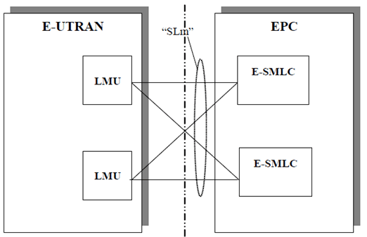
The overall architecture for UE positioning is described in TS 36.305. The E-UTRAN network based positioning architecture consists of a set of LMUs (either standalone or eNB-integrated LMUs as described in TS 36.305) contained in the E-UTRAN connected to the E-SMLC in the EPC through the SLm.
This subclause specifies only the architecture of the SLm interface, and shall not constrain the network architecture of either core or radio access networks.
The SLm interface is specified at the boundary between the LMUs and the E-SMLC. Figure 1 depicts the logical division of the SLm interface. From the SLm perspective, the E-UTRAN access point is an LMU, and the EPC access point is the E-SMLC.

The E-UTRAN may thus have several SLm access points towards the EPC. As a minimum, each SLm access point (in E-UTRAN or EPC) shall independently fulfil the requirements of the relevant SLm specifications (36.x1x series - see clause 7).
SLm is a logical interface.
There is only one SLm logical interface between an LMU and a given E-SMLC. However, an LMU can be connected to multiple E-SMLCs using different logical SLm interfaces.
4.2 SLm interface general principles p. 7
The general principles for the specification of the SLm interface are as follows:
- the SLm interface should be open;
- the SLm interface shall support the exchange of signalling information between the LMU and E-SMLC;
- from a logical standpoint, the SLm is a point-to-point interface between an LMU within the E-UTRAN and an E-SMLC in the EPC. A point-to-point logical interface should be feasible even in the absence of a physical direct connection between the LMU and E-SMLC.
4.3 SLm interface specification objectives p. 7
The SLm interface specification shall facilitate the following:
- inter-connection of E-SMLCs with LMUs supplied by different manufacturers;
- separation of SLm interface Radio Network functionality and Transport Network functionality to facilitate introduction of future technology.
4.4 SLm interface capabilities p. 7
The SLm interface supports:
- procedures to establish, maintain and release connections between the E-SMLC and LMUs;
- the separation of each LMU on the protocol level for specific signalling management;
- location services by transferring location requests from the E-SMLC to LMUs, and UL RTOA measurements from LMUs to E-SMLC;
4.5 SLm interface characteristics p. 8
4.5.1 Use of SCTP p. 8
The SCTP (RFC 4960) is used to support the exchange of SLm Application Protocol (SLmAP) signalling messages between an LMU and an E-SMLC.
5 Functions of the SLm interface protocol p. 8
5.1 General p. 8
The following sections describe the functions to fulfil the SLm interface capabilities.
5.2 SLm link management function p. 8
The SLm signalling link management function provides a reliable transfer of the signalling between LMU and E-SMLC.
5.3 SLm interface management function p. 8
The error indication function is used by the LMU (respectively the E-SMLC) to indicate to the E-SMLC (respectively the LMU) that a logical error has occurred.
The reset procedure is used to initialize the peer entity after node setup and after a failure event has occurred. This procedure can be initiated by the E-SMLC or the LMU. The information about the LMU capabilities after a reset is preserved in the E-SMLC.
The SLm Setup procedure allows the exchange of application level data, e.g. capability, needed for the LMU and E-SMLC to interoperate correctly on the SLm interface. This procedure is originated by the LMU only and initiates the setup of the SLmAP contexts to the E-SMLC.
5.4 SLm location function p. 8
The location function is used by the E-SMLC to request the LMU to perform UL RTOA measurements. The LMU reports UL RTOA measurements back to the requesting E-SMLC.
6 SLm interface protocol structure p. 8
6.1 General p. 8
The network signalling over SLm consists of the SLm Application Protocol (SLmAP). The SLmAP consists of mechanisms to handle all procedures between the E-SMLC in the EPC and LMUs in the E-UTRAN.
Over the SLm interface the SLmAP protocol is, e.g., used to:
- Request LMUs to perform UL RTOA measurements of target UE SRS transmissions.
- Transfer of completed UL RTOA measurements from the LMU to the E-SMLC.
6.2 SLmAP p. 9
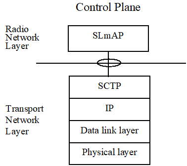
Figure 6.1 shows the protocol structure for SLmAP, following the structure described in TS 36.305.

The Transport Network Layer is based on IP transport, comprising SCTP on top of IP.
7 Other SLm interface specifications p. 9
7.1 E-UTRAN SLm interface: layer 1 (3GPP TS 36.457) p. 9
3GPP TS 36.457 specifies the physical layer technologies that may be used to support the SLm interface.
7.2 E-UTRAN SLm interface: signalling transport (3GPP TS 36.458) p. 9
3GPP TS 36.458 specifies the signalling bearers for the SLmAP for the SLm interface.
7.3 E-UTRAN SLm Interface: SLmAP Specification (3GPP TS 36.459) p. 9
3GPP TS 36.459 specifies the SLmAP for radio network control plane signalling over the SLm interface.