Content for TS 32.421 Word version: 19.0.0
0 Introduction
1 Scope
2 References
3 Definitions, symbols and abbreviations
3.1 Definitions
3.2 Abbreviations
...
...
0 Introduction p. 6
The present document is part of a TS-family covering the 3rd Generation Partnership Project; Technical Specification Group Services and System Aspects; Telecommunication management, as identified below:
TS 32.421:
Subscriber and equipment trace provide very detailed information at call level on one or more specific mobile(s).
This data is an additional source of information to Performance Measurements and allows going further in monitoring and optimisation operations.
Contrary to Performance measurements, which are a permanent source of information, trace is activated on user demand for a limited period of time for specific analysis purposes.
Trace plays a major role in activities such as determination of the root cause of a malfunctioning mobile, advanced troubleshooting, optimisation of resource usage and quality, RF coverage control and capacity improvement, dropped call analysis, Core Network and Access Network end-to-end procedure validation.
The capability to log data on any interface at call level for a specific user (e.g. IMSI) or mobile type (e.g. IMEI or IMEISV), or service initiated by a user allows getting information which cannot be deduced from Performance measurements such as perception of end-user QoS during his call (e.g. requested QoS vs. provided QoS), correlation between protocol messages and RF measurements, or interoperability with specific mobile vendors.
Moreover, performance measurements provide values aggregated on an observation period; Subscriber and UE Trace give instantaneous values for a specific event (e.g. call, location update, etc.).
If performance measurements are mandatory for daily operations, future network planning and primary trouble shooting; Subscriber and UE Trace is the easy way to go deeper into investigation and network optimisation.
In order to produce this data, Subscriber and UE Trace are carried out in the NEs, which comprise the network. The data can then be transferred to an external system (e.g. an Operations System (OS) in TMN terminology, for further evaluation).
"Subscriber and equipment trace: Trace concepts and requirements";
TS 32.422:
"Subscriber and equipment trace: Trace control and configuration management";
TS 32.423:
"Subscriber and equipment trace: Trace data definition and management";
1 Scope p. 7
The present document describes the requirements for the management of Trace and the reporting of Trace data (including FDD mode and TDD mode) across UMTS, EPS or 5G networks as it refers to subscriber tracing (tracing of IMSI or Public User Identity) and equipment tracing (tracing of IMEI or IMEISV). Trace also includes the ability to trace all active calls in a cell or multiple cells (Cell Traffic Trace). The present document also includes the description of Service Level Tracing (tracing of a specific service). It defines the administration of Trace Session activation/deactivation by the management system, the network or User Equipment (UE) itself via signalling, the generation of Trace results in the Network Elements (NEs) and UE and the transfer of these results to one or more Operations Systems.
GSM Trace is outside of the scope of this specification (see TS 52.008).
Furthermore, it describes requirements for Random Access (RA) Report, Successful Handover Report (SHR), Successful PSCell Change Report (SPR), Mobility History Information (MHI) Report and VisitedCellInfoList reporting for 5G networks.
The present document also describes the requirements for the management of Minimization of Drive Tests (MDT) across UMTS networks, EPS networks or 5G networks and Radio Link Failure (RLF) and RRC Connection Establishment Failure (RCEF) reporting across EPS networks and 5G networks.
The present document is built upon the basic Subscriber and UE Trace concept described in clause 4.
The high-level requirements for Trace data, Trace Session activation/deactivation and Trace reporting are defined in clause 5. Clause 5 also contains an overview of use cases for Trace (the use cases are described in Annex A). Clause 6 defines the requirements for managing MDT. Clause 7 defines the requirements for managing RLF, RCEF, RA, SHR, SPR, MHI and VisitedCellInfoList reports. Trace control and configuration management are described in TS 32.422, and Trace data definition and management are described in TS 32.423.
The present document does not cover any Trace capability limitations within a NE (e.g. maximum number of simultaneous traced mobiles for a given NE) or any functionality related to these limitations (e.g. NE aborting a Trace Session due to resource limitations).
The objectives of the Trace specifications are:
- to provide the descriptions for a standard set of Trace and MDT data;
- to produce a common description of the management technique for Trace, MDT, RLF, RCEF, RA, SHR, SPR, MHI and VisitedCellInfoList administration and result reporting;
- to define a method for the reporting of Trace, MDT, RLF, RCEF, RA, SHR, SPR, MHI and VisitedCellInfoList results across the management interfaces.
- tracing non-Subscriber or non-UE related events within an NE;
- tracing of all possible parties in a multi-party call (although multiple calls related to the IMSI specified in the Trace control and configuration parameters are traceable).
- It is accepted that the recorded information from the shared nodes is available to the Primary Operator. Recorded information that is collected in a non shared node or cell will only be available to the operator managing the non shared node or cell.
- It is accepted that the recorded information from the shared network shall be delivered to the Participating Operator whose PLMN recording is requested, taking user consent into account. Operators must also agree on sharing the information, but how that agreement is done is outside the scope of this specification. The mapping of TCE IP addresses and TCE addresses must be coordinated among the operators that shares the network. How that coordination is done is outside the scope of this specification.
- It is accepted that the inter-PLMN recorded information for Logged MDT from the non-shared nodes of Participating Operators may be available to the Primary Operator.
- For signalling based activation, the operators that share a network must coordinate the TCE IP addresses and the TCE address mapping must be coordinated. How that coordination is done is outside the scope of this specification.
2 References p. 8
The following documents contain provisions, which, through reference in this text, constitute provisions of the present document.
- References are either specific (identified by date of publication, edition number, version number, etc.) or non-specific.
- For a specific reference, subsequent revisions do not apply.
- For a non-specific reference, the latest version applies. In the case of a reference to a 3GPP document (including a GSM document), a non-specific reference implicitly refers to the latest version of that document in the same Release as the present document.
[1]
TS 32.101: "Telecommunication management; Principles and high level requirements".
[2]
TS 32.422: "Telecommunication management; Subscriber and equipment trace: Trace control and configuration management".
[3]
TS 32.423: "Telecommunication management; Subscriber and equipment trace: Trace data definition and management".
[4]
TS 23.002: "Network architecture".
[6] Void
[7]
TS 52.008: "Telecommunication management; GSM subscriber and equipment trace".
[8]
TR 21.905: "Vocabulary for 3GPP Specifications".
[9]
OMA Service Provider Environment Requirements, OMA-RD-OSPE-V1_0-20050614-C: The Open Mobile Alliance™ (URL:http://www.openmobilealliance.org/ ).
[10]
TS 33.401: "System Architecture Evolution (SAE); Security architecture".
[11]
TS 37.320: : "Universal Terrestrial Radio Access (UTRA) and Evolved Universal Terrestrial Radio Access (E-UTRA); Radio measurement collection for Minimization of Drive Tests (MDT); Overall description, Stage 2".
[12]
TS 32.450: "Key Performance Indicators (KPI) for Evolved Universal Terrestrial Radio Access Network (E-UTRAN): Definitions".
[13]
TS 32.130: "Network sharing; Concepts and requirements".
[14]
TS 36.300: "Evolved Universal Terrestrial Radio Access (E-UTRA) and Evolved Universal Terrestrial Radio Access Network (E-UTRAN); Overall description; Stage 2".
[15]
TS 23.501: "System Architecture for the 5G System; Stage 2".
[16]
TS 38.300: "NR and NG-RAN Overall Description; Stage 2".
[17]
TS 38.401: "NG-RAN; Architecture Description".
[18]
TS 36.331: "Evolved Universal Terrestrial Radio Access (E-UTRA) Radio Resource Control (RRC); Protocol Specification".
[19]
TS 25.331: "Radio Resource Control (RRC); protocol specification".
[20]
TS 38.413: "NG-RAN; NG Application Protocol (NGAP)".
[21]
TS 38.423: "NG-RAN; Xn Application Protocol (XnAP)".
[22]
TS 28.533: "Management and orchestration; Architecture framework".
[23]
TS 38.331: "NR; Radio Resource Control (RRC); Protocol specification".
3 Definitions, symbols and abbreviations p. 9
3.1 Definitions p. 9
For the purposes of the present document, the terms and definitions given in TS 21.905, TS 32.130, TS 23.501, TS 38.300 and the following apply:
Cell Traffic Trace:
The ability to trace one or more active calls in one or more cells.
Collection period:
Period that indicates the measurement results collection interval.
End user visible events:
Refer to OMA Service Provider Requirements [9].
Immediate MDT:
See TS 37.320.
Logged MDT:
See TS 37.320.
Management based activation/deactivation:
Trace Session is activated/deactivated in different NEs directly from the management system.
MDT measurements:
See TS 37.320.
MBSFN Area:
See TS 36.300.
MBSFN Area Reserved Cell:
See TS 36.300.
Signalling based activation/deactivation:
Trace Session is activated/deactivated in different NEs using the signalling interfaces between those elements so that the NEs may forward the activation/deactivation originating from the management system.
Measurement period:
Period that indicates the performance measurement reporting interval.
Trace:
general term used for Subscriber, Equipment and Service Trace.
Trace record:
in the NE a Trace record is a set of Traceable data collected as determined by the Trace control and configuration parameters.
Trace Recording Session:
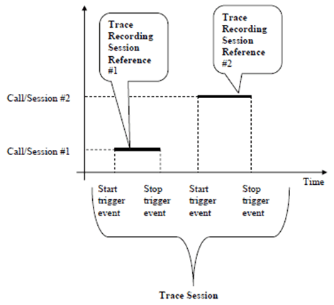
time interval within a Trace session while trace records are generated for the subscriber, UE or service being traced. The triggering events starting and stopping a Trace recording Session are defined in TS 32.422 (see Figure 1).
Trace Recording Session Reference:
identifies a Trace Recording Session within a Trace Session (see Figure 1)

Note that overlapping calls/sessions are possible for e.g. Cell Traffic Trace.
Trace Reference:
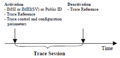
identifies a Trace Session and is globally unique (see Figure 2)
Trace Session:
time interval started with a Trace Session Activation and lasts until the Deactivation of that specific Trace Session (see Figure 2)

Trace Parameter Configuration:
a technique whereby a request for tracing a certain Subscriber, UE or Service is sent by the management system to the NE for execution.
Trace Parameter Propagation:
a technique by which the NE processes the trace configuration (received from the management system or another NE) and sends it to the relevant Network Element(s) via signalling interface(s).
Service Level Tracing:
Refer to OMA Service Provider Requirements [9].
3.2 Abbreviations p. 11
For the purposes of the present document, the abbreviations given in TR 21.905, TS 32.101, TS 32.130, TS 23.501, TS 38.300 and the following apply:
MHI
Mobility History Information
RA
Random Access
RCEF
RRC Connection Establishment Failure
RLF
Radio Link Failure
SHR
Successful Handover Report
SPR
Successful PSCell Change Report
TCE
Trace Collection Entity
SCGF
Secondary Cell Group Failure