Content for TS 32.295 Word version: 18.0.0
5 Transfer principles and scenarios p. 12
5.1 Transfer principles p. 12
5.1.0 General |R12| p. 12
The GTP' protocol is optional, and is used for CDR transport between the CDFs and the CGF.
5.1.1 Charging related transfer requirements p. 12
Each CDF has an OAM&P configurable address list of CGFs (Charging Gateways) to which it can send its CDRs. The list is organized in CGF address priority order. If the primary CGF is not available (e.g. out of service), then the CDF shall send the CDRs to the secondary CGF and so on.
Each CDR generating function only sends the records to the CGF(s) of the same PLMN, not to CGF(s) located in other PLMNs.
Each CGF in the PLMN may know of other CGFs' network addresses (e.g., for redundancy reasons, to be able to recommend another CGF address). This is achieved by OAM&P configuration facilities that enable each CGF to have a configurable list of peer CGF addresses.
5.1.2 CDR transport by GTP' p. 12
GTP' has been designed to deliver the CDR(s) from the CDF, which generates CDRs to the CGF(s). This protocol is required if the CGF resides outside the CDFs. It utilizes some aspects of GTP (defined in
TS 29.060), which is used for packet data tunnelling in the backbone network.
GTP' operates on the Ga interface and does not imply the use of any specific backbone network.
GTP' performs the following functions:
- CDR transfer between the CDF and the CGF.
- Redirection of CDRs to another CGF.
- Detect communication failures between the communicating peers, using echo messaging.
- Advertise to peers about its CDR transfer capability (e.g., after a period of service downtime).
- Prevents duplicate CDRs that might arise during redundancy operations.
5.1.2.1 CDF - CGF communication p. 13
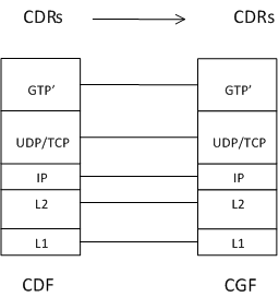
As illustrated in Figure 5.1.2.1.1, the CDF - CGF communications are carried out using GTP' over UDP/TCP and IP.
5.1.2.2 CGF - CGF communication p. 13
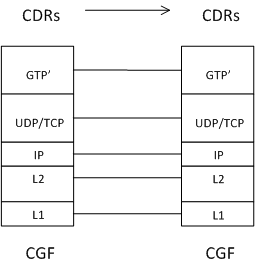
If necessary, CGF to CGF communications are carried out using GTP' over UDP/TCP and IP.
This is illustrated in Figure 5.1.2.2.1.
5.1.3 Port usage p. 14
Transporting the CDRs from the CDFs to the CGF over the Ga reference point may facilitate charging.
The Path Protocol may be UDP (compliant with STD 0006 [404]) or TCP (compliant with STD 0007 [405]) over IP.
-
UDP as the Path Protocol
Ports for signalling the request messages:
- The UDP Destination Port may be the server port number 3386 which has been reserved for GTP'. Alternatively another port can be used, which has been configured by OAM&P, except Port Number 2123 which is used by GTPv2-C.
- The UDP Source Port is a locally allocated port number at the sending network element.
- The UDP Destination Port value shall be the value of the Source Port of the corresponding request message.
- The UDP Source Port shall be the value from the Destination Port of the corresponding request message.
- TCP as Path Protocol The TCP Destination Port may be the server port number 3386, which has been reserved for G-PDUs. Alternatively, another port may be used as configured by OAM&P. Extra implementation-specific destination ports are possible but all CGFs shall support the server port number. The TCP Source Port is a random port, locally assigned at the sending network element.
- Network layer and lower layers Beneath the Path Protocol there is the network IP layer, which shall be the Internet Protocol (IP) compliant with STD 0005 (see [406] and [407]). Beneath the network IP layer are the L2 and L1 layers, which are not specified, in the present document.
5.2 GTP' transfer scenarios p. 15
5.2.1 Basic principles p. 15
Each function (i.e. CDF and CGF) that supports the GTP' shall be capable of handling or responding with a "Service/Version not supported" message if that function is configured to be addressed by another peer function.
5.2.2 GTP' messaging cases p. 15
5.2.2.0 General |R12| p. 15
The following example cases represent the three different key "Data Record Transfer Request/Response" messaging related CDR handling schemes. Cases (2) and (3) represent situations involving the redundancy mechanism.
- The normal CDR packet transfer: The CDF sends successfully a CDR packet to the CGF, and since the CDF gets a response (Request Accepted) for the Data Record Transfer Request, there is no need to use the CGF redundancy mechanism and redirect the CDR packet traffic flow to another CGF.
- The CDF-CGF connection breaks before a successful CDR reception: In this case the CDR packet sent by the CDF is lost before it is received by the CGF. (The loss might be caused by a link failure or e.g. a major CGF failure.)
- The CDF-CGF connection breaks after a successful CDR reception: In this case the CDR sent by the CDF is received correctly by the CGF and moved to its non-volatile memory (or even to the next NE in the communication chain). Anyhow, the CDF-CGF communication stops working, in this example case, before the CDF gets the positive response (Data Record Transfer Response: Request Accepted) which would acknowledge that the CDR packet was successfully received by CGF.
- CGF redundancy mechanism An overview on the mechanism, involved in cases (2) and (3), preventing duplicated CDR packets to enter a BD. The next four clauses describe in more detail each of these key "Data Record Transfer Request / Response" messaging schemes.
5.2.2.1 The normal CDR packet transfer p. 16
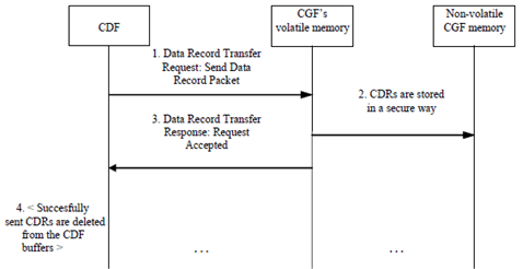
Figure 5.2.2.1.1 shows the default mode of CDR transfer from the CDR generating functions (CDFs) to the CDR collecting functions (CGFs).
Step 1.
The general principle of GTP' to retransmit the request if the response has not been received within a configurable time-out limit, is also followed here in point 1). The maximum amount of retries is a configurable value.
The CDR generating entity sends CDR(s) in a packet to CGF (that is the current primary Charging Gateway Functionality for the specific CDF, "CGF1"). The sending is performed by using the Data Record Transfer Request message, with the Packet Transfer Command IE having the value "Send Data Record Packet".
Step 2.
The CGF opens the received message and stores the packet contents in a safe way (to e.g. a redundant RAM memory unit or a mirrored non-volatile memory or even to another node).
Step 3.
The CDR receiving entity (CGF) sends confirmation of the successful packet reception to the CDF.
The confirmation is performed by using the Data Record Transfer Response message, with the Cause value being "Request Accepted".
Step 4.
After the positive response "Request Accepted" is received by the CDF, it may delete the successfully sent CDRs from its send buffer.
5.2.2.2 The CDF-CGF connection breaks before a successful CDR reception p. 17
Figure 5.2.2.2.1 shows the exceptional case when the CDR transfer from a CDR generating entity (CDF) to the primary CDR packet collecting entity (CGF1) fails in a way that the CGF1 is not able to store the CDR packet sent by the CDF. (The reason for the failure in packet transfer may be e.g. a link failure between the CDF and CGF1, or a capacity exhausting error in the storage device of CGF1, or a general CGF1 system failure or CGF1 maintenance break.)
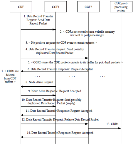
Figure 5.2.2.2.1: Duplicate prevention case: CDR sending via CGF1 had not succeeded
(⇒ copy of original 3GPP image)
(⇒ copy of original 3GPP image)
Step 1.
After all the potentially duplicated packets are cleared from CGF(s), the CDF can continue in normal way the transfer of CDRs.
The CDR generating entity (CDF) sends CDR(s) in a packet to CGF (that is, the current primary CGF for the specific CDF, "CGF1"). The sending is performed by using the Data Record Transfer Request message, with the Packet Transfer Command IE having the value "Send Data Record Packet".
Step 2.
Due to a failure in the CDF-CGF1 communication link of CGF1, the CGF1 is not able to store the packet sent by the CDF in a safe way (to e.g. a redundant RAM memory unit or a mirrored non-volatile memory or to another node).
Step 3.
Therefore the CDF is not able to get a response (or it could alternatively get a negative response like "No resources available" as the Cause value in the Data Record Transfer Response message).
Step 4.
The CDF may now first test the CDF-CGF2 link by an Echo Request message that the CGF2 would respond by the Echo Response.) Then, the CDF sends the same CDR packet that could not be sent to CGF1 to the next CGF in its CGF preference list (here CGF2) using the Data Record Transfer Request message, with the Packet Transfer Command IE having the value "Send possible duplicated Data Record Packet".
Step 5.
As the connection to the CGF2 is working, the CGF2 is able to process the CDR packet. Since the packet was marked by the sending CDF to be potentially duplicated, it is stored into the CGF2, but not yet sent forward towards the BD.
Step 6.
The CGF2 sends confirmation of the successful packet reception to the CDF. The confirmation is performed by using the Data Record Transfer Response message, with the Cause value being "Request Accepted"
Step 7.
The CDF can now delete the now successfully sent (potentially duplicated) CDRs from its CDR buffer (but it keeps the sequence number(s) of the sent potentially duplicated packet(s) in a buffer dedicated for that.
Step 8.
When CGF1 is recovering after a system reboot, it sends a Node Alive Request message to the configured peer CDF(s), and so the CDF notices that it can again successfully communicate with the CGF1. (The CDF may also detect this by using the Echo Request messages, which would be answered by CGF1 by the Echo Response message.)
Step 9.
CDF acknowledges the CGF1 by Node Alive Response message.
Step 10.
For the earlier unacknowledged Data Record Transfer Request message(s), the CDF sends CGF1 empty test packet(s) (with no CDR payload in the Data Record Packet IE but just the other parts of the message frame).
Step 11.
CGF1 responds with Data Record Transfer Response message, with the Cause value being "Request Accepted", because in this example case CGF1 had lost the communication capability towards CDF before storing the previously received (and by CGF1 unacknowledged) CDR packet.
Step 12.
Now CDF knows that the CGF1 had not originally been able to process and forward the original version of the CDR packet from the CDF, and it indicates CGF2 that CGF2 can send the CDR packet(s) related to the previously unacknowledged GTP' Sequence Number(s) to post-processing. Those packets' Sequence Numbers are indicated in the Sequence Numbers of the Released Packets IE.
Step 13.
CGF2 shall now be able to send the released records towards the post-processing system.
Step 14.
CGF2 responds with Data Record Transfer Response message, with the Cause value being 'Request Accepted'.
5.2.2.3 The CDF-CGF connection breaks after a successful CDR reception p. 19
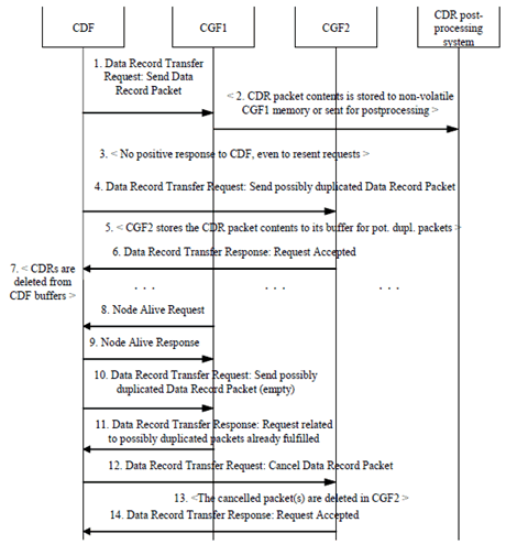
Figure 5.2.2.3.1: Duplicate prevention case: CDR sending via CGF1 had succeeded
(⇒ copy of original 3GPP image)
(⇒ copy of original 3GPP image)
Step 1.
After all the potentially duplicated packets are cleared form CGF(s), the CDF can continue in normal way the transfer of CDRs.
The CDR generating entity (CDF) sends CDR(s) in a packet to CGF (that is the current primary Charging Gateway Functionality for the specific CDF, "CGF1"). The sending is performed by using the Data Record Transfer Request message, with the Packet Transfer Command IE having the value "Send Data Record Packet".
Step 2.
The CGF1 is able to store the packet sent by the CDF in a safe way (to e.g. a redundant RAM memory unit or a mirrored non-volatile memory or to another network element, e.g. post-processing system).
Step 3.
Since the CDF-CGF1 communication connection is now broken, the CDF is not able to get the response "Request Accepted" as the Cause value in the Data Record Transfer Response message.
Step 4.
Then the CDF sends the same CDR packet that could not be sent to CGF1 to the next CGF in its CGF preference list (here CGF2) a Data Record Transfer Request message, with the Packet Transfer Command IE having the value "Send possible duplicated Data Record Packet". (That sending may be preceded by the testing of the CDF-CGF2 link by an Echo Request message; that the CGF2 would respond by the Echo Response.)
Step 5.
As the connection to CGF2 is working, CGF2 is able to process the CDR packet. Since the packet was marked by the sending CDF to be potentially duplicated, it is stored in CGF2, but not yet sent forward towards the post processing or BD.
Step 6.
The CGF2 sends confirmation of the successful packet reception to the CDF. The confirmation is performed by using the Data Record Transfer Response message, with the Cause value being "Request Accepted".
Step 7.
The CDF can now delete the now successfully sent (potentially duplicated) CDRs from its CDR buffer (but it keeps the sequence number(s) of the sent potentially duplicated packet(s) in a buffer dedicated for that.
Step 8.
When CGF1 is recovering after a system reboot, it sends a Node Alive Request message to the configured peer CDF(s), and so the CDF notices that it can again successfully communicate with the CGF1. (The CDF may also detect this by using the Echo Request messages, which would be answered by CGF1 by the Echo Response message.)
Step 9.
CDF acknowledges the CGF1 by Node Alive Response message.
Step 10.
For the earlier unacknowledged Data Record Transfer Request message(s), the CDF sends CGF1 empty test packet(s) (with no CDR payload in the Data Record Packet IE but just the other parts of the message frame).
Step 11.
CGF1 responds with Data Record Transfer Response message, with the Cause value being "Request related to possibly duplicated packets already fulfilled", because in this example case CGF1 had lost the communication capability towards CDF after storing the previously received (and by CGF1 unacknowledged) CDR packet.
Step 12.
Now CDF knows that the CGF1 had originally been able to process and forward the original version of the CDR packet from the CDF, and it indicates CGF2 that CGF2 can cancel the CDR packet(s) related to the previously unacknowledged GTP' CDF-CGF1 Sequence Number(s). Those packets' Sequence Numbers are indicated in the Sequence Numbers of the Cancelled Packets IE.
Step 13.
CGF2 shall now delete the cancelled packet(s) from its buffer for potentially duplicated packets.
Step 14.
CGF2 responds with Data Record Transfer Response message, with the Cause value being "Request Accepted".
5.2.2.4 CGF redundancy mechanism p. 21
A summary of the CGF redundancy mechanism, which prevents duplicated CDR packets to enter the BS,
is described below.
This, or other mechanisms, are deployed to enhance the reliability of CDR transport.
The general logic of the duplicate CDR packet prevention in CGF redundancy cases is shown in Figure 5.2.2.4.1, where the messages are numbered sequentially, alternative messages are indicated by an index character ("a" or "b") that follows the arrow sequence number. The main mechanism of the messaging in CGF redundancy cases (when a CDF-CGF link is down or a CGF is not working) is based on CDF (1) first trying to send a CDR packet to CGF1.
In case no acknowledgement or a successful response is received (2) from CGF1 due to any reason, e.g. such as the request not reaching CGF1 despite repeated attempts (or the responses from CGF1 to the CDF are lost after the CGF1 has either stored it securely, or, forwarded it towards post-processing (2b)), the unacknowledged CDR packets are redirected to CGF2. The invocation for a re-transmission may be triggered by a time-out mechanism.
The CDF may first test the CDF-CGF2 link by sending an 'Echo Request' message to CGF2, in response to which CGF2 would respond with the 'Echo Response' message. The CDR packets not successfully received by the primary CGF (=CGF1) are sent to CGF2 (3), and are marked as potential duplicates, and CGF2 responds to the request(s) (4). Such CDRs, i.e. CDRs that are marked as potential duplicates would wait there for further commands from CDF.
When the CDF detects (5) and (6) that the primary CGF, in this case CGF1 is again able to communicate with it on receiving Node Alive Request (or getting a Echo Response from CGF2 to a Echo Request sent by the CDF) it answers by Node Alive Response. Then the CDF tests CGF1 with an empty packet (7), retrying continuously if no response is received, using e.g. increasing timeouts (using the old unacknowledged packet's Sequence Number, if the CGF1 would consider the packet to be a new one (8a) or an already received one (8b)). According to the response received from CGF1, the CDF gives the CGF2 a command to either release (9a) or cancel (9b) the corresponding CDR packet from CGF2. CGF2 then confirms the decision (10), and is able to send the CDRs towards the BS (11a).
Error handling:
By default, retransmissions after configurable timeouts are used. If after the CGF1 communication failure, the CDR packet sending from CDF to CGF2 does not succeed, the CDF tries to use CGF3 as the intermediate CDR packet storage entity, etc. If no acknowledgement (10) is received by the CDF for its message(s) (9a) or (9b), the CDF retransmits the message (9a) or (9b) continuously and persistently, using e.g. increasing time intervals. An alarm should be sent to the OAM&P system if a communication link goes down. It shall be possible to release/cancel CDR packets from CGFs and unacknowledged sequence numbers from CDFs by OAM&P operations if permanent CDF-CGF link failures would occur. The buffers containing the Sequence Numbers of potentially duplicated packets, and the buffers containing the numbers of unacknowledged CDR packets shall be kept up to date (with CDR packet transfers) using transaction mechanisms. In the case of the CDF-CGF1 communication link being down, any new CDRs generated by the CDF are sent to a properly working CGF2, instead of the CGF1.
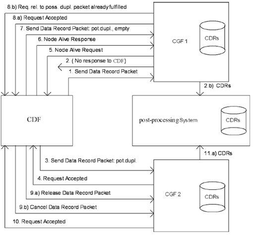
A more detailed description of the CGF redundancy mechanism:
Due to a network failure/ congestion or a temporary node failure, a CGF might not be able to send a response within the configured timeout period to a request it got from a CDF. As a first attempt, retries of requests are to be used as defined in TS 29.060, if the response is not received in the configured time.
If a CDF loses its connection to the CGF unexpectedly, it may send the CDRs to the next CGF in the priority list. If the CGF changes, the CDF can continue sending CDRs to different CGF nodes, depending on which CGF has been configured as the receiver of CDRs for a particular service.
Sequence number buffers:
The CDF might lose its connection to its primary CGF due to a link failure or CGF going down. In this kind of redundancy condition the CDF attempts to redirect the CDR traffic to a secondary CGF (after possible retries have failed). The CDF maintains an internal buffer for Sequence Numbers of requests not yet successfully responded to by the primary CGF, for the case that it may become capable of communicating to the primary CGF at a later date. The CDF sends the not responded Data Record Packets (DRPs) to the secondary CGF, and the CDF maintains also a buffer for the Sequence Numbers related to those DRPs that have been temporarily stored to this secondary CGF. (If the communication towards the secondary CGF would not work, the transfer of possibly duplicated DRPs and Sequence Number bookkeeping would be done for a tertiary CGF etc.) Also the CGFs maintain Sequence Number buffers for each of their CDF links. The Sequence Numbers may in future be needed in relation to the possibly duplicated CDRs that the CGFs have got from the CDF(s). The Sequence Numbers are stored to wait for a final decision to release them towards the BS (if the primary CGF had not received successfully the packets originally sent by a CDF) or to cancel them (if the primary CGF had received and processed successfully the originally by CDF sent packets).
The CDF is able to instruct CGF2 to cancel (or instruct CGF2 to transfer towards the BS), the CDR packets sent to a secondary CGF if the primary CGF becomes available for service. To make the right decision the CDF first sends an empty test packet with the 'Send possibly duplicated Data Record Packet' Packet Transfer Command to the primary CGF, using a previously not responded Sequence Number.
In case that the empty test packet to the primary CGF (which was temporarily down (or to which the link was down)) is responded with the Cause value "Request Accepted", the CDF releases the corresponding CDRs waiting for final decision in the secondary CGF, towards the BD with the Packet Transfer Command "Release Data Record Packet".
If the primary CGF responses this test message with the Cause value "Request related to possibly duplicated packets already fulfilled", the CDF cancels the corresponding CDRs waiting for final decision in the secondary CGF, using the Packet Transfer Command "Cancel Data Record Packet".
To enable that a CDF failure (destroying its Sequence Number buffers per each CGF link for non-responded requests or possibly duplicated packets) would not cause CDR packets to stay forever in the temporary decision waiting buffers of CGFs, there should also be OAM&P means of emptying those CGF buffers.
There shall also be a configurable parameter in the CGF for making the final decision, as to whether or not it is able to send the CDRs to the BS for the case where the backup buffering mechanism in the CDF could not be used until the end of the messaging sequence related to a certain CDR packet has been completed. This way the operator can:
- Select that the CDFs and CGFs take care of duplicate prevention and the BS is not required to do duplicate checking due to possible duplicates caused by Network Element or CGF redundancy mechanisms.
- Select that the BS performs the duplicate prevention. To do this in the most effective way, the CGF may include an additional flag linked to possibly duplicated CDRs sent to the BS, indicating that they have not been released by a CDF for BS use (or use special kind of file name if a file protocol is used between CGF and BS). This means that the BS has somewhat more processing work to do, but the BS would anyway get a duplicate free end result. CGF is in this case always authorized to forward CDRs towards the BS, also when they contain possibly duplicated data. For this case the CGFs may also have a configurable flag that Data Record Packet Cancel/Release operations are not needed.