Content for TS 27.005 Word version: 18.0.0
0 Scope p. 7
The present document defines three interface protocols for control of SMS functions within a GSM/UMTS mobile telephone from a remote terminal via an asynchronous interface.
Clause 2 defines a binary protocol ("Block Mode"). The protocol includes error protection and is suitable for use where the link may not be completely reliable. It will be of particular use where control of remote devices is required. Efficient transfer of binary encoded user data is possible.
Clause 3 defines a character-based interfaced based on "AT" commands ("Text Mode"). This mode is suitable for unintelligent terminals or terminal emulators, and for application software built on command structures like those defined in V.25ter. Some of the commands defined in clause 3 will also be useful for implementations of clause 2 and/or clause 4, for example enabling an indication of incoming SMS messages.
Clause 4 defines a character-based interface with hex-encoded binary transfer of message blocks ("PDU Mode"). This mode is suitable for software drivers based on AT command structures which do not understand the content of the message blocks and can only pass them between the MT and "upper level" software resident in the TE.
In all three modes, the terminal is considered to be in control for SMS/CBS transactions.
The present document considers the mobile termination to be a single entity. Other 3GPP/GSM Technical Specifications describe the split of functionality between the mobile equipment and (U)SIM.
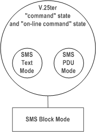
The three "modes" referred to above, are represented in Figure 0.1.
The "Block mode" is a self contained mode in its own right, and when entered, control will remain within that mode until the procedures to exit the mode are executed, after which control is returned to the V.25ter "command" state or "on-line command" state.
The "Text" and "PDU" modes are not in themselves V.25ter states but are simply sets of commands which will operate in either the V.25ter "command" state or "on-line command" state. The "Text" and "PDU" modes are transitory states and after each operation, control is automatically returned to the V.25ter "command" state or "on-line command" state. Whilst in the V.25ter command state, the MS is available to handle incoming and outgoing calls such as Data or Facsimile.

In the "Block mode" and "PDU" mode a mobile is not permitted to modify any component of an SMS/CBS message received from the air interface or an SMS message received from a TE, before passing it on, except where TS 23.040 or TS 23.041 defines a "component modification facility" and where this "component modification facility" is supported by the mobile. In the Text Mode the mobile may be unable to display characters coded in particular coding schemes. In this case, the mobile shall behave as described in TS 23.038 and assume the coding scheme to be the GSM 7 bit default alphabet.
0.1 References p. 8
The following documents contain provisions which, through reference in this text, constitute provisions of the present document.
- References are either specific (identified by date of publication, edition number, version number, etc.) or non-specific.
- For a specific reference, subsequent revisions do not apply.
- For a non-specific reference, the latest version applies. In the case of a reference to a 3GPP document (including a GSM document), a non-specific reference implicitly refers to the latest version of that document in the same Release as the present document.
[1] Void.
[2]
TS 23.038: "Alphabets and language-specific information".
[3]
TS 23.040: "Technical realization of the Short Message Service (SMS) ".
[4]
TS 23.041: "Technical realization of the Cell Broadcast Service (CBS)".
[5]
TS 24.008: "Mobile Radio Interface Layer 3 specification; Core Network Protocols; Stage 3".
[6]
TS 24.011: "Short Message Service (SMS) support on mobile radio interface".
[7]
TS 24.012: "Cell Broadcast Service (CBS) support on the mobile radio interface".
→ to date, withdrawn by 3GPP
[8]
→ to date, withdrawn by 3GPP
TS 27.001: "General on Terminal Adaptation Functions (TAF) for Mobile Stations (MS)".
[9]
TS 27.007: "AT command set for User Equipment (UE)".
[10]
TS 51.011: "Specification of the Subscriber Identity Module - Mobile Equipment (SIM - ME) interface".
[11]
ITU-T Recommendation V.25ter: "Serial asynchronous automatic dialling and control".
[12]
ITU-T Recommendation V.24: "List of definitions for interchange circuits between data terminal equipment (DTE) and data circuit-terminating equipment (DCE)".
[13]
ITU-T Recommendation E.164: "The international public telecommunication numbering plan".
[14]
ITU-T Recommendation E.163: "Numbering plan for the international telephone service".
[15]
TR 21.905: "Vocabulary for 3GPP Specifications".
[16]
TS 31.102: "Characteristics of the USIM application".
0.2 Abbreviations p. 8
For the purposes of the present document, the abbreviations given in TR 21.905 and the following] apply.
EVPF
Enhanced Validity Period Format
1 Reference configuration p. 9

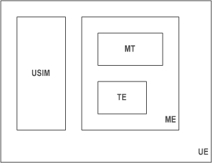
The User Equipment (UE) consists of the mobile equipment (ME) and the (U)SIM. Messages may be stored in either, but the present document does not distinguish between messages stored in the (U)SIM or in the ME. The management of message storage in the two parts of the UE is a matter for the UE implementation.
1.1 V.24 Interface Circuits p. 9
The operation of the ITU-T Recommendation V.24 blue book interface circuits for SMS is shown in Table 1.1.
| V.24 CIRCUIT | DESCRIPTION | TE to MT | MT to TE |
|---|---|---|---|
| CT102 | signal ground | x | x |
| CT103 | TXD | x | |
| CT104 | RXD | x | |
| CT105 | RTS | x | |
| CT106 | CTS | x | |
| CT107 | DSR | x | |
| CT108.2 | DTR | x | |
| CT109 | DCD | x | |
|
NOTE:
CT105 at the TE is connected to CT133 at the MT.
|
|||
1.1.1 Circuit definitions for the SMS Block mode p. 9
CT103
All commands from the TE to the MT are transferred across this circuit. Inband flow control is not permitted during Block Mode.
CT104
All responses/indications from the MT to the TE are transferred across this circuit. Inband flow control is not permitted during Block Mode.
CT105
This circuit allows the TE to flow control the MT when in the Block Mode and at other times if hardware flow control is enabled.
CT106
This circuit allows the MT to flow control the TE when in the Block Mode and at other times if hardware flow control is enabled.
CT107
This circuit shall be set to the ON condition before entry into the Block Mode, and shall remain in the ON condition during Block Mode. If the TE detects that this circuit returns to the OFF condition during the block mode then the TE shall return CT108.2 to the OFF condition and exit the Block Mode.
CT108.2
This circuit shall be set in the ON condition before the AT+CESP command is sent from the TE to begin the Block Mode, and shall be maintained in the ON condition during the Block Mode. It shall be returned to the OFF condition after the command 'END SMS MODE' has been accepted and acknowledged by the MT. If the MT detects that this circuit returns to the OFF condition during the Block Mode then the MT shall exit the Block Mode.
CT109
This circuit shall be set to the ON condition before entry into the Block Mode and remain in the ON condition during the Block Mode. If the TE detects that this circuit returns to the OFF condition during the Block Mode then the TE shall return CT108.2 to the OFF condition and shall exit the Block Mode.
1.1.2 Circuit definitions for the SMS Text and PDU modes p. 10
Only circuits CT102, CT103 and CT104 are mandatory for the Text and PDU modes. The functionality and operation of other circuits shall be in accordance with V.25ter.