Content for TS 25.111 Word version: 18.0.0
0 Introduction
1 Scope
2 References
3 Definitions and abbreviations
3.1 Definitions
3.2 Abbreviations
4 General
4.1 Main concepts
4.2 LMU Classes
4.3 U-TDOA architecture
...
...
0 Introduction p. 5
In order to ensure correctness and consistency of the specifications (i.e., technical specifications and technical reports) under responsibility of the Technical Specification Groups (TSG) of the 3rd Generation Partnership Project (3GPP), clear, manageable and efficient mechanisms are necessary to handle version control, change control, document updating, distribution and management.
Also, the fact that the specifications are/will be implemented by industry almost in parallel with the writing of them requires strict and fast procedures for handling of changes to the specifications.
It is very important that the changes that are brought into the standard, from the past, at present and in the future, are well documented and controlled, so that technical consistency and backwards tracing are ensured.
The 3GPP TSGs, and their sub-groups together with the Support Team are responsible for the technical content and consistency of the specifications whilst the Support Team alone is responsible for the proper management of the entire documentation, including specifications, meeting documents, administrative information and information exchange with other bodies.
1 Scope p. 6
The present document establishes the Location Measurement Unit (LMU) minimum RF characteristics of the FDD mode of UTRA.
2 References p. 6
The following documents contain provisions which, through reference in this text, constitute provisions of the present document.
- References are either specific (identified by date of publication, edition number, version number, etc.) or non-specific.
- For a specific reference, subsequent revisions do not apply.
- For a non-specific reference, the latest version applies. In the case of a reference to a 3GPP document (including a GSM document), a non-specific reference implicitly refers to the latest version of that document in the same Release as the present document.
3 Definitions and abbreviations p. 6
3.1 Definitions p. 6
For the purposes of the present document, the terms and definitions given in TR 21.905 and the following apply. A term defined in the present document takes precedence over the definition of the same term, if any, in TR 21.905.
Mean power:
When applied to a W-CDMA modulated signal this is the power (transmitted or received) in a bandwidth of at least (1+ α times the chip rate of the radio access mode. The period of measurement shall be at least one timeslot unless otherwise stated.
3.2 Abbreviations p. 6
For the purposes of the present document, the abbreviations given in TR 21.905 and the following apply. An abbreviation defined in the present document takes precedence over the definition of the same abbreviation, if any, in TR 21.905.
ACS
Adjacent Channel Selectivity
BS
Base Station
BER
Bit Error Ratio
BLER
Block Error Ratio
CW
Continuous Wave (unmodulated signal)
DL
Down Link (forward link)
FDD
Frequency Division Duplexing
GSM
Global System for Mobile Communications
LMU
Location Measurement Unit
UARFCN
UTRA Absolute Radio Frequency Channel Number
UE
User Equipment
UL
Up Link (reverse link)
U-TDOA
Uplink Time Difference Of Arrival
WCDMA
Wideband Code Division Multiple Access
4 General p. 7
4.1 Main concepts p. 7
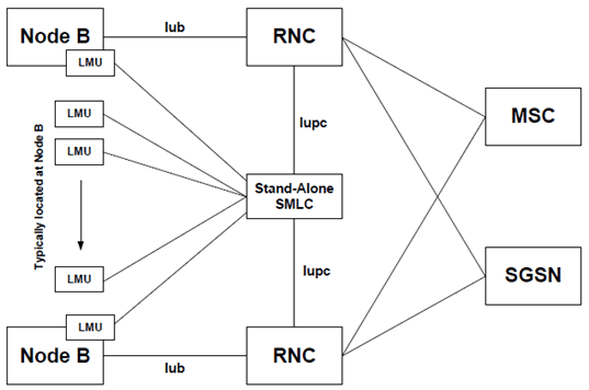
The LMU is either located as a separate unit in an existing network or typically located at Node B or BTS sites. Therefore the LMU radio requirements assume that the isolation between the LMU and any other network to be protected is to be at least 30dB.
The communication link between LMU and Stand-Alone SMLC is not a radio interface over the air. Requirements in this document therefore do not cover the situation when the LMU is transmitting over the air on this interface between LMU and Stand-Alone SMLC.
4.2 LMU Classes p. 7
The requirements in this specification apply to Wide Area LMUs and Medium Range LMUs.
Wide Area LMUs are characterised by requirements derived from Macro Cell scenarios with an LMU to UE minimum coupling loss equal to 70 dB.
Medium Range LMUs are characterised by requirements derived from Micro Cell scenarios with an LMU to UE minimum coupling loss equal to 53 dB.
For Pico Cell scenarios, the location of the BS provides sufficient accuracy; therefore, a Local Area LMUs class is not specified.
4.3 U-TDOA architecture p. 7
A sample architecture is shown in Figure 3.1 depicting the LMU's relationship with other network elements. The LMU is typically located at the Node B. The LMUs communicate with the SMLC that distributes UTDOA reference data from the reference LMU to other cooperating LMUs when performing UE positioning.
