Content for TS 23.279 Word version: 18.0.0
8.3 User adds an IMS service to an ongoing CS call
8.3.1 IMS session set up without media requiring resource reservation
8.3.2 IMS session set- up with media requiring resource reservation
...
...
8.3 User adds an IMS service to an ongoing CS call p. 18
8.3.1 IMS session set up without media requiring resource reservation p. 18
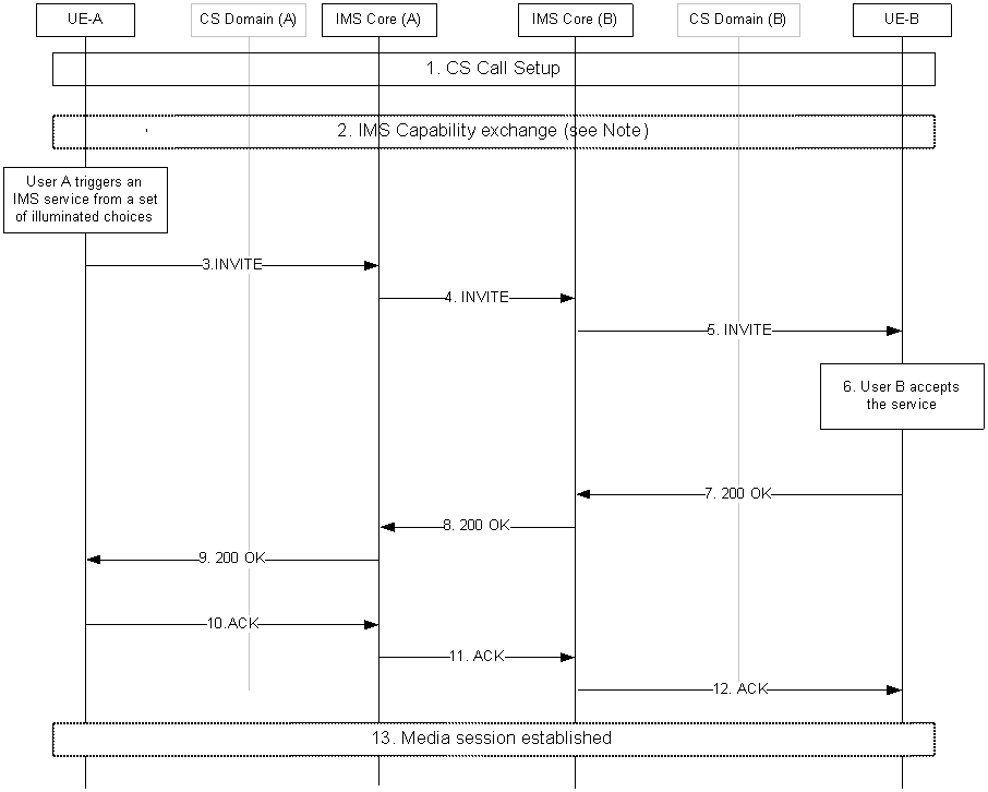
The following sequence diagram shows an IMS service being added to an ongoing CS call when the CSI capabilities of UE-B have not previously been stored by UE-A and are therefore exchanged after CS call setup.

Step 1.
A CS call is setup as per clause 8.1.
Step 2.
The UE-A should initiate an IMS capability exchange as described in clause 8.2.
Step 3.
The UE-A shall send the SIP INVITE request to the IMS Core along the signalling path established during registration.
Step 4.
The IMS Core (A) forwards the INVITE request to IMS Core (B).
Step 5.
The IMS Core (B) forwards the INVITE request to UE-B.
Step 6.
The UE-B shall associate the INVITE request with the ongoing CS call by using the MSISDN and SIP URI, obtained through the IMS Capability exchange procedure and/or included in the INVITE request
Step 7.
The UE-B invokes the correct application, which associates the SIP session with the ongoing call by matching the identities used in the CS call and the SIP session. The UE-B then sends a 200 OK.
Step 8.
The IMS Core (B) forwards the 200 OK to IMS Core (A).
Step 9.
The IMS Core (A) forwards the 200 OK to UE-A.
Step 10.
The UE-A acknowledges the 200 OK.
Step 11.
The IMS Core (A) forwards the acknowledgement to IMS Core (B).
Step 12.
The IMS Core (B) forwards the acknowledgement to UE-B.
Step 13.
Media as per the session setup is sent between the two UEs.
8.3.2 IMS session set- up with media requiring resource reservation p. 20
For an IMS session setup in the context of CSI it shall be possible to require media resource reservation as per procedures in TS 23.228, illustrated in the use case below.
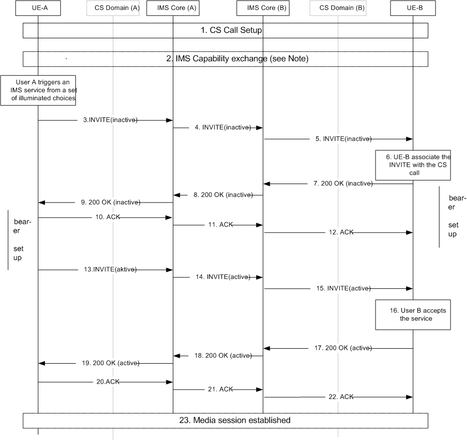
The following sequence diagram shows an IMS service being added to an ongoing CS call when the CSI capabilities of UE-B have not previously been stored by UE-A and are therefore exchanged after CS call setup. Only media resource reservation based on the "inactive" mechanism is shown.

Step 1.
A CS call is setup as per clause 8.1.
Step 2.
The UE-A should initiate an IMS capability exchange as described in clause 8.2. If UE-B does not receive any IMS capability exchange from UE-A within a certain time limit the UE-B should initiate the IMS capability exchange, if required.
Step 3.
The UE-A shall send the SIP INVITE request with the media components marked "inactive" to the IMS Core along the signalling path established during registration.
Step 4.
The IMS Core (A) forwards the INVITE request to IMS Core (B).
Step 5.
The IMS Core (B) forwards the INVITE request to UE-B.
Step 6.
The UE-B shall associate the INVITE request with the ongoing CS call by using the MSISDN and SIP URI, obtained through the IMS Capability exchange procedure and/or included in the INVITE request. If required, UE-B immediately initiates IP-CAN bearer setup. No alerting of user B needs to be carried out.
Step 7.
The UE-B directly sends a 200 OK with the media components marked 'inactive'.
Step 8.
The IMS Core (B) forwards the 200 OK to IMS Core (A).
Step 9.
The IMS Core (A) forwards the 200 OK to UE-A.
Step 10.
The UE-A initiates IP-CAN bearer setup for the media and acknowledges the 200 OK.
Step 11.
The IMS Core (A) forwards the acknowledgement to IMS Core (B).
Step 12.
The IMS Core (B) forwards the acknowledgement to UE-B.
Step 13.
The UE-A shall send the SIP INVITE request with the media components marked "active" to the IMS core when the IP-CAN bearer is established on UE-A access.
Step 14.
The IMS Core (A) forwards the INVITE request to IMS Core (B).
Step 15.
The IMS Core (B) forwards the INVITE request to UE-B.
Step 16.
The UE-B shall perform necessary service action to receive/send user plane media.
Step 17.
The UE-B shall send 200 OK with the media components marked 'active' when the IP-CAN bearer is setup and the UE is ready to receive media.
Step 18.
The IMS Core (B) forwards the 200 OK to IMS Core (A).
Step 19.
The IMS Core (A) forwards the 200 OK to UE-A.
Step 20.
The UE-A acknowledges the 200 OK.
Step 21.
The IMS Core (A) forwards the acknowledgement to IMS Core (B).
Step 22.
The IMS Core (B) forwards the acknowledgement to UE-B.
Step 23.
User plane connection is established.