Content for TS 23.218 Word version: 18.0.0
B Information flows for example services
B.1 Call forwarding example
B.1.1 Call forwarding through Application Servers
B.1.2 Assumptions
B.1.3 UE redirect based call flows
B.1.4 S-CSCF based redirect call flows
...
...
B Information flows for example services p. 51
This Annex contains some informative example information flows that show the possible flow of information for some example services. These examples are intended only to help aid the understanding of the behaviour of the S-CSCF, MRFC and Application Servers for service provision for the IM CN subsystem and are not intended to recommend or specify how to create such services, (indeed the examples given may not even be a good idea for a practical implementation).
The following modes of operation are shown in these examples:
- Third Party Registration to Application Server (subclause B.3.2);
- Application Server in Originating UA mode (subclause B.3.2);
- Application Server in Redirect mode (subclause B.1.3);
- Application Server in Terminating UA mode (subclause B.3.1);
- Application Server in Proxy mode (subclause B.1.4);
- Application Server in Third Party Call Control/B2BUA mode (subclause B.2.1, subclause B.2.2,and subclause B.2.3);
- Application Server with no involvement (subclause B.1.4).
B.1 Call forwarding example p. 51
B.1.1 Call forwarding through Application Servers p. 51
B.1.1.0 Introduction |R7| p. 51
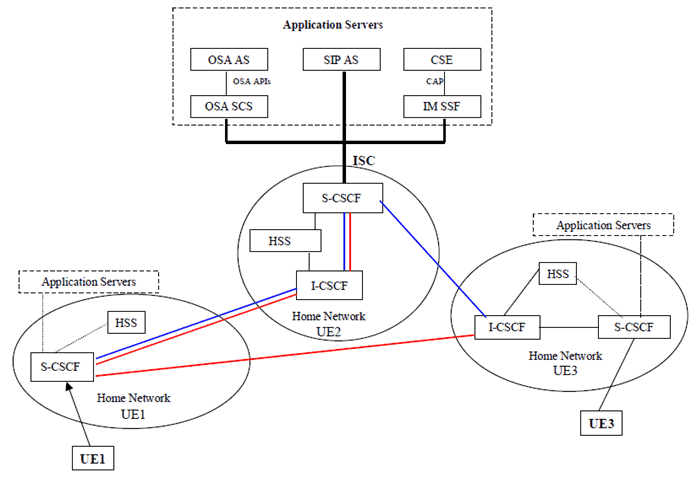
Figure B.1.1.1 presents the network configuration for a call-forwarding scenario. Some interfaces between nodes have been omitted purely for clarity. In this configuration, the UE1 originates a call to the UE2. The UE2 is subscribed to a Call Forwarding (CF) service based on the Calling Line Identification (CLI). The CF service logic resides in an Application Server interfacing to the IM CN subsystem via the ISC interface. The Application Server is programmed to detect all incoming calls or terminating sessions with UE1's CLI and to instruct the S-CSCF to forward the calls/sessions to another destination, UE3, either directly or via the UE1. These two session forwarding scenarios are shown by the red and blue coloured flows. When the session redirection is carried out directly by the S-CSCF of the UE2, the network may notify the UE1 of its call/session redirection.
As shown in Figure B.1.1.1, the Application Server may be a SIP AS, or an OSA AS or a CAMEL CSE. The latter two Application Servers interface the S-CSCF via the OSA SCS and IM SSF gateways, respectively.

Figure B.1.1.1: Network configuration for the call forwarding examples
(⇒ copy of original 3GPP image)
(⇒ copy of original 3GPP image)
In this configuration, the originating UE1 and the terminating UE3 are assumed to be in their respective home network. The UE2, not shown in Figure B.1.1.1, may be either at its home network or roaming in a visited network.
The CF feature is invoked based on the detection of the originating party's CLI "pre-activated" for call forwarding. Upon invocation of the CFonCLI feature, the call will be forwarded to a pre-specified destination. These two steps and a few underlying assumptions are briefly described below:
B.1.1.1 Service activation and programming p. 52
The UE2 activates its CFonCLI service and programs it with a Forward-to Number which is UE3's number, conditioning it to the originating party's line identity, CLI.
B.1.1.2 Service invocation and control p. 52
The UE1 makes a call to the UE2. The CFonCLI is invoked and the call is forwarded to the UE3 following a "Session Redirection" that is initiated by either the S-CSCF or the UE1.
B.1.2 Assumptions p. 53
For the CFonCLI service invocation and service control procedure, the following are assumed to hold:
- Normal case scenario, showing successful cases only;
- Subscriber data of all three UE1, UE2 and UE3 are stored in their respective HSS;
- All call/session control for the UE1, UE2, and UE3 is done in their respective home network S-CSCF;
- The UE2 has already subscribed to the CFonCLI service with a service provider operating an Application Server where the service control logic resides;
- The pre-selected numbers (e.g., UE3) to which the originated calls are forwarded, are stored by the CFonCLI service control logic upon activation of the feature by the UE2.
B.1.3 UE redirect based call flows p. 53

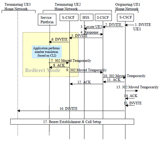
Figure B.1.3.1 presents the information flow for the invocation and control of the CFonCLI service based on the configuration of Figure B.1.1.1.
The UE1 initiates a call to UE2. The CFonCLI service logic is invoked in the Application Server when the S-CSCF for UE2 detects that service invocation is required. The call is forwarded to the UE3 by the UE1 according to the "Session Redirection initiated by UE" procedure. The UE3 accepts the (forwarded) call. A detailed description for each flow is given below:
Step 1.
The S-CSCF of UE1 receives a SIP INVITE request form UE1.
Step 2.
The I-CSCF of the UE2 receives a SIP INVITE request form the S-CSCF of the originating user, UE1. UE1's CLI is included in this INVITE request.
Step 3.
The I-CSCF of the UE2 queries the HSS to obtain the S-CSCF of the UE2.
Step 4.
The HSS returns the S-CSCF location.
Step 5.
The I-CSCF forwards the INVITE request to the S-CSCF of UE2.
Step 6.
Based on the information obtained from the UE2 Service Profile (during registration), the S-CSCF of the UE2 detects that the criteria for certain pre-defined triggers are met. The INVITE request is forwarded to the Application Server. The service logic is invoked in the Application Server.
Step 7.
Based on the outcome of the execution of the service logic, the Application Server instructs the S-SCSF to REDIRECT the session to UE3. The behaviour of the Application Server follows the description of a 'redirect server'. It sends the 302 Move Temporary response with UE3 as the redirect address to UE1. The Application Server plays no further part in the session establishment.
Step 8.
S-CSCF of UE2 sends ACK request back to the Application Server to acknowledge the receiving of the 302 (Moved Temporarily) response.
Step 9.
S-CSCF of UE2 forwards the 302 (Moved Temporarily) response to the I-CSCF of UE2.
Step 10.
The I-CSCF of UE2 forwards the 302 Move Temporary to the S-CSCF of UE1.
Step 11.
The S-CSCF of UE1 sends ACK request to acknowledge the receiving of the 302 Move Temporary.
Step 12.
The I-CSCF of UE2 forwards the ACK request to the S-CSCF of UE2.
Step 13.
The S-CSCF of UE1 forwards the 302 (Moved Temporarily) response to the next downstream hop.
Step 14.
The S-CSCF of UE1 receives the ACK request for that 302 (Moved Temporarily) response from the downstream hop.
Step 15.
The UE1 re-issues an INVITE request with UE3 as the destination.
Step 16.
The originating S-CSCF redirects the SIP INVITE request to the UE3's home network.
Step 17.
Bearer establishment & call setup between from the UE1 to the UE3 is performed following the procedure described in the basic call flow sections for originating, inter-network and terminating segments.
B.1.4 S-CSCF based redirect call flows p. 54
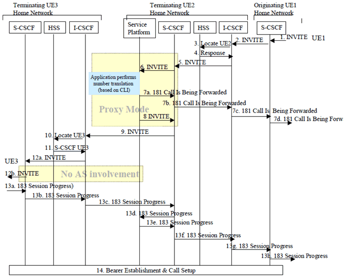
Figure B.1.4.1 presents the information flow for the invocation and control of the CFonCLI service based on the configuration of Figure B.1.1.1, where redirection is made by the S-CSCF after instructions from the service logic in the Application Servers.

The UE1 (located in the originating visited network) makes a call to UE2. The CFonCLI is invoked and the CFonCLI service logic is executed by an application residing in the Application Server.
The call is forwarded to the UE3 by the S-CSCF of UE2 according to the "Session Redirection" instructed by the Application Server. The S-CSCF sends a SIP 181Call Is Being Forwarded to UE1 and a SIP INVITE request to UE3. The UE3 accepts the (forwarded) call. A detailed description for each flow is given below:
Step 1) - 6.
are identical to flows by the same number in the UE Redirect example provided in B.1.3.
Step 7a, 7b, 7c and 7d.
The Application Server notifies the UE1 that the call is being forwarded, by sending a 181 (Call Is Being Forwarded) response.
Step 8.
The service logic forwards the INVITE request back to S-CSCF modifies the destination address by inserting the identity of the UE3. The Application Server is in SIP proxy mode.
Step 9.
The S-CSCF of UE2 forwards the modified INVITE request it received from the Application Server to the I-CSCF of UE3.
Step 10.
The I-CSCF of the UE3 queries the HSS to obtain the S-CSCF of the UE3.
Step 11.
The HSS returns UE3's S-CSCF location.
Step 12a and 12b.
The I-CSCF forwards the SIP INVITE request the UE3 via its S-CSCF.
Step 13a, 13b, 13c, 13d, 13e, 13f, 13g, 13h and 13g.
The UE3 accepts the incoming call and sends an 183 (Session Progress) response back to UE1.
Step 14.
Bearer establishment & call setup between from the UE1 to the UE3 is performed following the procedure described in the basic call flow subclauses for originating, inter-network and terminating segments.