Content for TS 23.146 Word version: 18.0.0
A Structure and contents of the FA protocol elements
A.1 Internet Fax Protocol
A.2 Facsimile UDP Transport Layer Protocol
A.3 User Datagram Protocol
A.4 Internet Protocol
A.5 Point to Point Protocol
A.6 Mapping of FA frames
A (Normative) Structure and contents of the FA protocol elements p. 26
A.1 Internet Fax Protocol p. 26
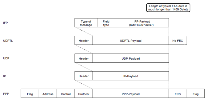
This ANNEX is related to the application of the T.38 protocol within the present document.
Only the following packets are used:
-
T30_INDICATOR
- CNG
- CED
- TCF error detection (not in T.38)
- FA_busy_packet (not in T.38)
- FA_non_busy_packet (not in T.38)
-
T30_DATA
- V.21 channel 2 (except MCF, CFR, RTN, RTP, PIP, PIN, PRI, PPR, NSF, NSC, RR, RNR, ERR)
- V.27 ter 2400
- V.27 ter 4800
- V.29 7200
- V.29 9600
- V.17 7200
- V.17 9600
- V.17 12000
- V.17 14400
A.2 Facsimile UDP Transport Layer Protocol p. 26
The FEC option and the redundant message option shall not be used.
A.3 User Datagram Protocol p. 26
The port number at client side is ephemeral (assigned on a call by call basis). The port number at the server side is manually preassigned by the operator.
A.4 Internet Protocol p. 27
The IP address is not required because a circuit switched connection is used between the UE and IWF. However, IP addresses shall be used in order to be consistent with IP.
The IP address at UE side and IWF side are assigned by PPP.
A.5 Point to Point Protocol p. 27
For the communication between the two FAs IP is provided on top of PPP.
PPP shall conform to RFC 1662, 1661, 1570 and 1332.
A.6 Mapping of FA frames p. 27
Refer also to TS 27.002.

