TS 23.014
Dual Tone Multi-Frequency (DTMF) Signalling
V18.0.0 (PDF)
2024/03 14 p.
V17.0.0
2022/03 14 p.
V16.0.0
2020/06 14 p.
V15.0.0
2018/06 14 p.
V14.0.0
2017/03 14 p.
V13.0.0
2015/12 14 p.
V12.0.0
2014/09 14 p.
V11.0.0
2012/09 14 p.
V10.0.0
2011/03 14 p.
V9.0.0
2009/12 14 p.
V8.0.0
2008/12 14 p.
V7.0.0
2007/06 14 p.
V6.0.0
2005/01 14 p.
V5.1.0
2002/09 14 p.
V4.1.0
2002/09 14 p.
V3.2.0
2002/09 14 p.
GSM Rel-98 v7.0.1
1999/06 10 p.
GSM Rel-97 v6.0.0
1998/10 10 p.
GSM Rel-96 v5.0.0
1996/10 13 p.
GSM Phase-2 v4.1.1
1994/09 14 p.
GSM Phase-1 v3.0.2
1992/02 11 p.
- Rapporteur:
- Mr. Leis, Peter
Nokia Networks
Content for TS 23.014 Word version: 18.0.0
1 Scope
2 References
3 Abbreviations
4 Requirement
5 Cause of DTMF generation
6 Support of DTMF across the air interface
6.1 General
6.2 Specific
6.3 Tone durations
7 Effect of Handover
7.1 Internal Handover
7.2 External Handover
$ Change history
1 Scope p. 5
The present document describes how Dual Tone Multi Frequency (DTMF) signals are supported in the 3GPP system.
2 References p. 5
The following documents contain provisions which, through reference in this text, constitute provisions of the present document.
- References are either specific (identified by date of publication, edition number, version number, etc.) or non-specific.
- For a specific reference, subsequent revisions do not apply.
- For a non-specific reference, the latest version applies. In the case of a reference to a 3GPP document (including a GSM document), a non-specific reference implicitly refers to the latest version of that document in the same Release as the present document.
[1] Void.
[1a]
TR 21.905: "Vocabulary for 3GPP Specifications".
[2]
TS 45.002: "Multiplexing and Multiple Access on the Radio Path".
[3]
ETSI ES 201 235-1, v1.1.1: "Specification of Dual Tone Multi-Frequency (DTMF); Transmitters and Receivers; Part 1: General".
[4]
ETSI ES 201 235-2, v1.2.1: "Specification of Dual Tone Multi-Frequency (DTMF); Transmitters and Receivers; Part 2: Transmitters".
[5]
ETSI ES 201 235-3, v1.2.1: "Specification of Dual Tone Multi-Frequency (DTMF); Transmitters and Receivers; Part 3: Receivers".
[6]
ITU-T Recommendation H.245: "Control protocol for multimedia communication"
3 Abbreviations p. 5
For the purposes of the present document, the abbreviations used in the present document are listed in TR 21.905.
4 Requirement p. 5
Dual Tone Multi Frequency (DTMF) is an inband one out of four plus one out of four signalling system, primarily used from terminal instruments in telecommunication networks. The international recommendations which apply are ETSI ES 201 235 [3], [4], [5] as detailed in subclause 6.2 and subclause 6.3. For PCS 1900 for North America the Standards which apply are operator specific.
In the 3GPP system the MSC must support DTMF in the mobile to land direction.
The support of this facility in the land to mobile direction is for further study.
The use of DTMF is only permitted:
- when the speech teleservice is being used or during the speech phase of alternate speech/data and alternate speech/facsimile teleservices; the DTMF is transmitted across the radio interface as specified in subclause 6 of this specification; and
- during a multimedia call; the DTMF is transmitted across the radio interface using the H.245 UserInputIndication message (see ITU-T H.245 [6]). This is transparent for the MSC.
5 Cause of DTMF generation p. 6
A user may cause a DTMF tone to be generated by depression of a key in the Mobile Station (MS). Optionally (on a MS basis) manufacturers of mobile equipment may choose to allow DTMF to be controlled from a remote terminal.
The man-machine interface questions associated with this facility are not discussed further in the present document.
6 Support of DTMF across the air interface p. 6
6.1 General p. 6
A message based signalling system is used across the 3GPP system air interface.
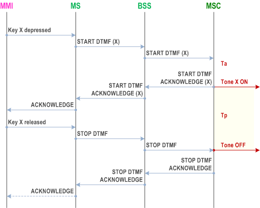
This requires that the relevant user action (e.g. a key depression) is interpreted by the MS as a requirement for a DTMF digit to be sent, this is converted by the MS into a message, the message is transmitted across the air interface, and is converted by the MSC into a DTMF tone which is applied towards the network, which should then respond with an acknowledgement. When the user completes the key depression, an message that the DTMF sending should cease is also passed to the MSC, which again will respond with an acknowledgement.
6.2 Specific p. 6
The messages to be sent across the air interface will use the frame stealing mode of transmission.
The messages when sent across the air interface should contain the following information:
- START DTMF: Containing the digit value (0-9, A, B, C, D, *, #);
- START DTMF ACKNOWLEDGE: Containing the digit value (0-9, A, B, C, D, *, #) corresponding to the DTMF tone that the network applies towards the remote user;
- STOP DTMF: No further info;
- STOP DTMF ACKNOWLEDGE: No further info.
- Frequencies are defined in ETSI ES 201 235-1 [3] (for PCS 1900 for North America this is operator specific);
- Tone sending levels are defined in ETSI ES 201 235-2 [4] (for PCS 1900 for North America this is operator specific);
- Durations as specified below.
6.3 Tone durations p. 7
The network shall ensure that the minimum length of tone and the minimum gap between two subsequent tones according to ETSI ES 201 235-2 [4] is achieved. For PCS 1900 for North America this is operator specific.
There is no defined maximum length to the tone, which will normally cease when a STOP DTMF message is received from the MS. However, the operator may choose to put a pre-defined time limit on the duration of tones sent to line as mentioned in clause 6.2.
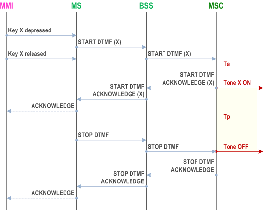
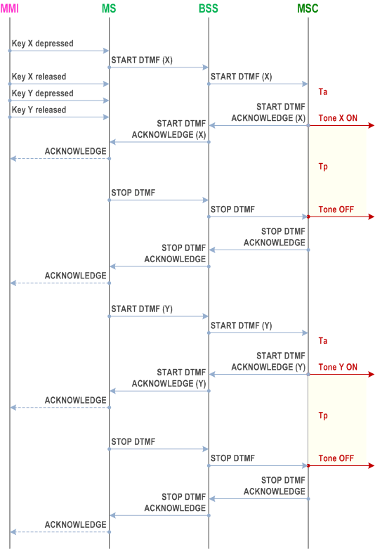
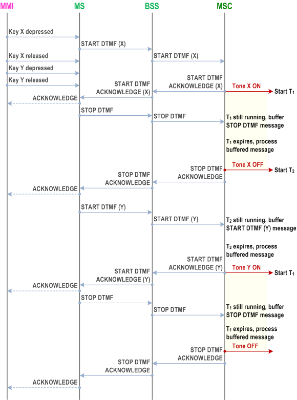
Figures 1 to 3 show an overview of how the DTMF should operate.

Ta
Association time for DTMF Generator in MSC, implementation dependent but low.
Tp
Pre-determined maximum tone length, operator option.
T1
Minimum length of tone.

Ta
Association time for DTMF Generator in MSC, implementation dependent but low.
Tp
Pre-determined maximum tone length, operator option.
T1
Minimum length of tone.

Ta
Association time for DTMF Generation in MSC, implementation dependant but low.
Tp
Pre-determined maximum tone length, operator option.
T2
Minimum gap between tones.

T1
Minimum length of tones
T2
Minimum gap between tones.
7 Effect of Handover p. 10
7.1 Internal Handover p. 10
There is unlikely to be any impact on DTMF due to internal handover.
7.2 External Handover p. 11
Depending on the exact moment when handover occurs, there may be a slight possibility of cutting short a DTMF tone.
For protocol reasons, in the case of an MSC receiving a STOP DTMF message when no tone is being sent, it should respond with an acknowledgement as usual.
No other impact is seen due to external handover.