Content for TR 22.835 Word version: 18.2.0
5.9 Regionally different resources for network slices
5.9.1 Description
5.9.2 Pre-conditions
5.9.3 Service Flows
5.9.4 Post-conditions
5.9.5 Existing features partly or fully covering the use case functionality
5.9.6 Potential New Requirements needed to support the use case
...
...
5.9 Regionally different resources for network slices p. 25
5.9.1 Description p. 25
Installation of radio equipment needs a lot of work to be done. Thus, typically, even if an operator owns a certain radio frequency nationally, the operator may gradually deploy radio equipment one region by one region, expanding coverage gradually. As a result, even if some network slice, for example, such as a slice for IMS service is provided nationally, the used frequency band for that network slice may be different per different areas.
5.9.2 Pre-conditions p. 26
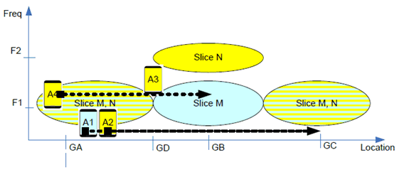
Figure 5.9.2-1 shows the use case scenario where network slices use different radio resources for different areas.

In this figure, it is assumed that
-
Subscription and configuration:
- UE A1 has a subscription to slice M.
- UE A2, A3 and A4 have subscription to slice N.
-
Deployment:
- F1 is used at all areas. F2 is available only at area around GB, e.g. in a highly populated area.
- Due to high demand of applications related to Slice N, at area around GB, frequency F2 is dedicated to serve the network slice N, and F1 is dedicated to serve other network slices such as network slice M.
5.9.3 Service Flows p. 26
Following is service flow for UE A1 and A2 which move from area GA to area GC:
- UE A1 and A2 are serviced with network slices over F1 at area GA.
- UE A1 continues to be serviced with network slice M over F1 toward area GB. Because F1 at area GB does not support slice N, the network moves the UE A2 to F2 to provide service continuity for network slice N from area near GD. While the frequency used for Slice N changes, the service interruption to applications over Slice N is minimized.
- UE A1 continues to be serviced with network slice M over F1 toward area GC. UE A2 moves back to F1 to get network slice N from as the UE moves along from GB to GC. While the frequency used for Slice N changes, the interruption to application over Slice N is minimized.
- UE A3 is located at the boundary area where the used frequencies for a network slice N differ. To prevent unnecessary power consumption, service interruption and increased signaling, frequency change between F1 and F2 needs to be minimized, when the UE A3 is serviced with network slice N.
- UE A4 is serviced with network slice N over F1 at area GA. When application ends, the user of UE A4 switches off the UE A4.
- While the UE A4 is switched off, the user moves from the area GA to the area GB.
- When the user arrives at the area GB, the user turns on the UE A4 and starts finds cells, beginning with F1 which is the last used frequency.
- The UE A4 finds out that F1 does not support Slice N. In the end, the UE access cells on F2 and gets service for network slice N over F2 at area GB.
5.9.4 Post-conditions p. 27
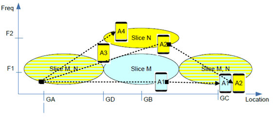
Following Figure 5.9.4-1 shows the status at the end of service flow.

5.9.5 Existing features partly or fully covering the use case functionality p. 27
Following are service requirements that can be drawn out of service description in previous sections and that can be supported with existing specifications:
- 3GPP shall support the same network slice to be configured over different frequencies at different areas.
- 3GPP shall support service continuity for a network slice at the boundary where radio resources configured for the network slice change, for a UE in Connected mode.
- 3GPP shall support to minimize the time that takes for a UE to be able to access radio resource configured for a network slice when the used radio resources for the network slice change e.g. during mobility, power cycle.
- 5G system shall support a mechanism to minimize service interruption for a UE when different radio resources are configured for a network slice in different geographical areas and when the UE crosses the geographic area boundaries.
5.9.6 Potential New Requirements needed to support the use case p. 27
No new requirement is derived from this use case.