Content for TR 38.877 Word version: 18.1.0
5.3 Wideband antenna architectures p. 22
5.3.1 General p. 22
Antenna arrays are resonant structures. The optimum radiating element size (a dipole is nominally λ/2) and the array element separation are both dependent on frequency. If an antenna is required to operate over a broad range of frequencies it is difficult to maintain optimum element size and element spacing over the whole range. The required percentage bandwidth of the multi-band signal in Table 5.1-1 is therefore important when looking at the feasibility of a broadband antenna.
From antenna design perspective, solutions covering multiple bands can be achieved in three main ways: a single broadband design covering the entire range of the bands (trades certain performance parameters), designing an antenna with multiple resonances in the desired bands, or having separate antenna designs each covering a band (lower percentage bandwidth
5.3.2 Single array bandwidth p. 23
It can be noted for comparison that there are FR1 multi-band fixed antenna arrays covering 1710MHz to 2690MHz, with a percentage bandwidth of 44.5% (VSWR of < 1.5:1). Fixed antenna arrays (with no or limited beam steering) however have more flexibility on element separation with values of up to 0.9λ being acceptable as the grating lobe is also fixed and can be attenuated with the element pattern. Whilst FR1 antennas build practices are different, the limitations on element size and spacing between elements are similar to those for FR2.
The radiating element can trade bandwidth against radiation performance. Short dipoles still radiate but the performance degrades the farther from the ideal frequency they are operated at. Defining an exact "acceptable" level of radiation efficiency for a broadband product is not straightforward as other aspects have to be considered (some radiation efficiency may be traded to achieve a broadband system). Also, as the element becomes smaller, its radiation pattern becomes broader these negating its ability to act as a spatial filter for array grating lobes.
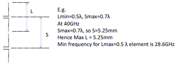
The size of the radiating element and the element separation are also dependent, e.g. the elements cannot touch each other. The separation of the elements in terms of wavelength occurs at the highest frequency, as the maximum separation is limited by the grating lobe performance there is an upper limit to how large this separation may be. Therefore, this sets the maximum size of the element (which will be electrically shortest at the lowest frequency).

Figure 5.3.2-0: Example of physical limitations of element size and separation
(⇒ copy of original 3GPP image)
(⇒ copy of original 3GPP image)
The maximum separation is also a parameter which is difficult to agree as it depends on a number of things, a fixed antenna array may have a separation of up to 0.9λ (at its maximum operational frequency). In previous studies [xx] it has been assumed for BS antenna simulations that a fully steerable antenna array has a separation of 0.5-0.7λ to avoid grating lobes.
For example, taking 0.5λ as a lower limit (this could be smaller if short dipoles were used), it then needs to be decided what an acceptable level of side lobe / grating lobe suppression is and also what range of steering is required.
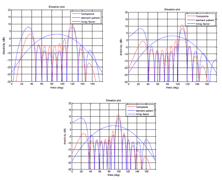
Three examples with similar grating lobe levels and different element spacing and steering can be seen:
- 0.7λ element separation with 30° steering
- 0.8λ element separation with 20° steering
- 0.9λ element separation with 10° steering

Figure 5.3.2-1: Array pattern: 0.7λ element separation with 30° steering, 0.8λ element separation with 20° steering, 0.9λ element separation with 10° steering
(⇒ copy of original 3GPP image)
(⇒ copy of original 3GPP image)
Each of these maximum separations equates to a percentage BW of 33%, 46% and 57%, respectively, and it is clear that grating lobe level and steering range can be traded against percentage bandwidth. Once again, selecting an exact set of conditions to estimate a maximum percentage bandwidth is difficult as it depends on the product definition.
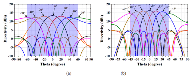
Using another approach and taking antenna element separation 0.5λ at a higher limit, the scanning angle reaches ±60° at 26 GHz and ±45° at 38 GHz with acceptable side lobe/grating lobe levels, as shown in Figure 5.3.2-2. The corresponding spacing will be 0.34λ at a lower limit. The isolation among the antenna elements at a lower limit can be ensured with the use of decoupling structures.

Figure 5.3.2-2: Beam scanning performance in azimuth plane when antenna element separation is 0.5λ at higher limit (a) 26 GHz, and (b) 38 GHz
(⇒ copy of original 3GPP image)
(⇒ copy of original 3GPP image)
In addition to the physical limitations and grating lobe performance discussed, it should also be noted that the array is electrically shorter at lower frequencies than higher frequencies and this also affects the antenna directivity and gain. For example, there is approximately 3dB gain difference between low band (26GHz) and high band (38GHz) that can be seen in Figure 5.3.2-2. This factor may also be a consideration when planning an antenna design.
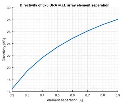
Taking another example, Figure 5.3.2-3 shows the directivity of an 8x8 uniform rectangular phased array with respect to different element separations. The antenna elements described in [31] are used in the simulation. It is seen that lower element separation will result in low array directivity. This means if the separations seen by lower frequency band is low, it likely consumes more energy to deliver acceptable array performance and cause power imbalance with higher bands, while the EIS receiver sensitive is low. The directivity difference between operating frequency bands may also be a consideration when planning an antenna design.

Figure 5.3.2-3:. Directivity of uniform rectangular array (URA) with respect to array element separations
(⇒ copy of original 3GPP image)
(⇒ copy of original 3GPP image)
The coupling effect may also pose challenges in wideband antenna array designs. It should be further noticed that the lower and higher band will see different impact of the mutual coupling effect among radiators due to different element spacing, i.e. the narrower element spacing suffers stronger mutual coupling. This effect could change the array pattern and input impedance matching of the antenna elements while being difficult to analytically predict.
However, based on existing technology it has been agreed that multi-band AA with common radiated element with 19.5% percentage bandwidth in frequency range 24-29 GHz which includes n257/n258/n261, or with 26.3% percentage bandwidth in frequency range 37-48 GHz which includes n260/n259/n262 is feasible, at least from antenna array perspective.