Content for TS 37.340 Word version: 17.3.0
1…
4…
4.2…
4.3…
5…
7…
8…
9
10…
10.2…
10.2.2…
10.3…
10.3.2
10.4…
10.5…
10.5.2
10.6
10.7…
10.8…
10.9…
10.10…
10.11…
10.12…
10.12.2
10.13…
10.14…
10.15
10.16…
10.17…
10.18…
10.19…
11…
A
B…
10.2 Secondary Node Addition p. 30
10.2.1 EN-DC p. 30
The Secondary Node Addition procedure is initiated by the MN and is used to establish a UE context at the SN to provide resources from the SN to the UE. For bearers requiring SCG radio resources, this procedure is used to add at least the first cell of the SCG. This procedure can also be used to configure an SN terminated MCG bearer (where no SCG configuration is needed). In case of CPA, the Conditional Secondary Node Addition procedure can be used for CPA configuration and CPA execution.
Secondary Node Addition
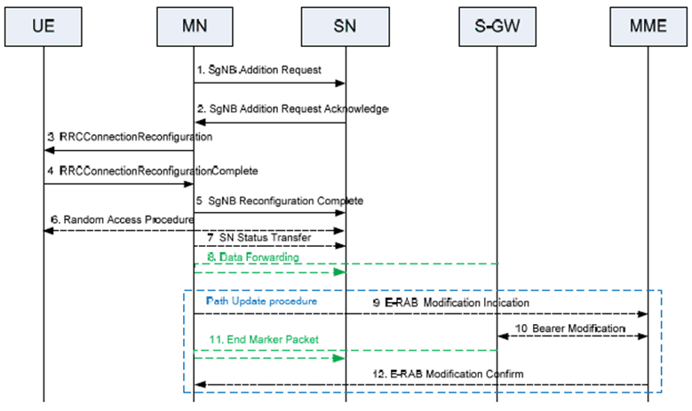
Figure 10.2.1-1 shows the Secondary Node Addition procedure.

Step 1.
Conditional Secondary Node Addition
The MN decides to request the SN to allocate resources for a specific E-RAB, indicating E-RAB characteristics (E-RAB parameters, TNL address information corresponding to bearer type). In addition, for bearers requiring SCG radio resources, MN indicates the requested SCG configuration information, including the entire UE capabilities and the UE capability coordination result. In this case, the MN also provides the latest measurement results for SN to choose and configure the SCG cell(s). The MN may request the SN to allocate radio resources for split SRB operation. The MN always provides all the needed security information to the SN (even if no SN terminated bearers are setup) to enable SRB3 to be setup based on SN decision. In case of bearer options that require X2-U resources between the MN and the SN, the MN provides X2-U TNL address information for the respective E-RAB, X2-U DL TNL address information for SN terminated bearers, X2-U UL TNL address information for MN terminated bearers. In case of SN terminated split bearers the MN provides the maximum QoS level that it can support. The MN may request the SCG to be activated or deactivated. The SN may reject the addition request.
Step 2.
If the RRM entity in the SN is able to admit the resource request, it allocates respective radio resources and, dependent on the bearer option, respective transport network resources. For bearers requiring SCG radio resources, the SN triggers Random Access so that synchronisation of the SN radio resource configuration can be performed. The SN decides the PSCell and other SCG SCells and provides the new SCG radio resource configuration to the MN in a NR RRC configuration message contained in the SgNB Addition Request Acknowledge message. In case of bearer options that require X2-U resources between the MN and the SN, the SN provides X2-U TNL address information for the respective E-RAB, X2-U UL TNL address information for SN terminated bearers, X2-U DL TNL address information for MN terminated bearers. For SN terminated bearers, the SN provides the S1-U DL TNL address information for the respective E-RAB and security algorithm. If SCG radio resources have been requested, the SCG radio resource configuration is provided. If the MN requested the SCG to be deactivated, the SN may keep the SCG activated. If the MN requests the SCG to be activated, the SN shall keep the SCG activated.
Step 3.
The MN sends to the UE the RRCConnectionReconfiguration message including the NR RRC configuration message, without modifying it. Within the MN RRCConnectionReconfiguration message, the MN can indicate the SCG is deactivated.
Step 4.
The UE applies the new configuration and replies to MN with RRCConnectionReconfigurationComplete message, including a NR RRC response message, if needed. In case the UE is unable to comply with (part of) the configuration included in the RRCConnectionReconfiguration message, it performs the reconfiguration failure procedure.
Step 5.
The MN informs the SN that the UE has completed the reconfiguration procedure successfully via SgNB ReconfigurationComplete message, including the encoded NR RRC response message, if received from the UE.
Step 6.
If configured with bearers requiring SCG radio resources and the SCG is not deactivated, the UE performs synchronisation towards the PSCell of the SN. The order the UE sends the RRCConnectionReconfigurationComplete message and performs the Random Access procedure towards the SCG is not defined. The successful RA procedure towards the SCG is not required for a successful completion of the RRC Connection Reconfiguration procedure.
Step 7.
If PDCP termination point is changed to the SN for bearers using RLC AM, and when RRC full configuration is not used, the MN sends the SN Status Transfer message.
Step 8.
For SN terminated bearers moved from the MN, dependent on the bearer characteristics of the respective E-RAB, the MN may take actions to minimise service interruption due to activation of EN-DC (Data forwarding).
Step 9-12.
If applicable, the update of the UP path towards the EPC is performed.

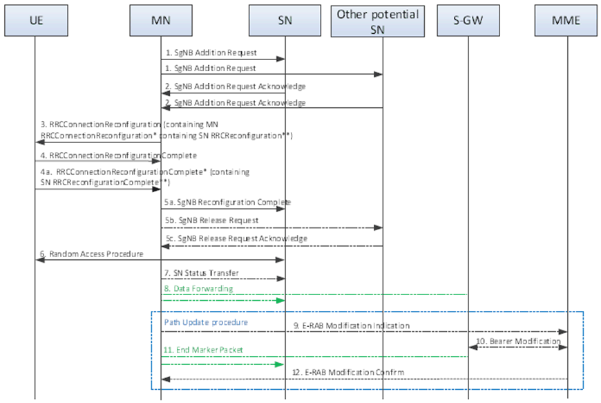
Step 1.
The MN decides to configure CPA for the UE and requests the candidate SN(s) to allocate resources for a specific E-RAB, indicating E-RAB characteristics (E-RAB parameters, TNL address information corresponding to bearer type), indicating that the request is for CPAC and providing the upper limit for the number of PSCells that can be prepared by the candidate SN. In addition, for the bearers requiring SCG radio resources, the MN indicates the requested SCG configuration information, including the entire UE capabilities and the UE capability coordination result. In this case, the MN also provides the candidate cells recommended by MN via the latest measurement results for the candidate SN to choose from and configure the SCG cell(s). The MN may request the candidate SN to allocate radio resources for split SRB operation. The MN always provides all the needed security information to the candidate SN (even if no SN terminated bearers are setup) to enable SRB3 to be setup based on SN decision. In case of bearer options that require X2-U resources between the MN and the candidate SN, the MN provides X2-U TNL address information for the respective E-RAB, X2-U DL TNL address information for SN terminated bearers, X2-U UL TNL address information for MN terminated bearers. In case of SN terminated split bearers the MN provides the maximum QoS level that it can support. The candidate SN may reject the addition request.
Step 2.
If the RRM entity in the candidate SN is able to admit the resource request, it allocates respective radio resources and, dependent on the bearer option, respective transport network resources, and provides the prepared PSCell ID(s) to the MN. For bearers requiring SCG radio resources, the candidate SN configures Random Access so that synchronisation of the SN radio resource configuration can be performed at the CPA execution. From the list of cells indicated within the measurement results provided by the MN, the candidate SN decides the list of PSCell(s) to prepare (considering the maximum number indicated by the MN) and, for each prepared PSCell, the candidate SN decides SCG SCells and provides the corresponding SCG radio resource configuration to the MN in an NR RRCReconfiguration** message contained in the SgNB Addition Request Acknowledge message. The candidate SN can either accept or reject each of the candidate cells listed within the measurement results indicated by the MN, i.e. it cannot configure any alternative candidates. In case of bearer options that require X2-U resources between the MN and the candidate SN, the candidate SN provides X2-U TNL address information for the respective E-RAB, X2-U UL TNL address information for SN terminated bearers, X2-U DL TNL address information for MN terminated bearers. For SN terminated bearers, the candidate SN provides the S1-U DL TNL address information for the respective E-RAB and security algorithm. If SCG radio resources have been requested, the SCG radio resource configuration is provided.
Step 3.
The MN sends to the UE an RRCConnectionReconfiguration message including the CPA configuration, i.e. a list of RRCConnectionReconfiguration* messages and associated execution conditions. Each RRCConnectionReconfiguration* message contains the SCG configuration in the RRCReconfiguration** message received from the candidate SN in step 2 and possibly an MCG configuration. Besides, the RRCConnectionReconfiguration message can also include an updated MCG configuration, e.g., to configure the required conditional measurements.
Step 4.
The UE applies the RRCConnectionReconfiguration message received in step 3, stores the CPA configuration and replies to the MN with an RRCConnectionReconfigurationComplete message. In case the UE is unable to comply with (part of) the configuration included in the RRCConnectionReconfiguration message, it performs the reconfiguration failure procedure.
Step 4a.
The UE starts evaluating the execution conditions. If the execution condition of one candidate PSCell is satisfied, the UE applies RRCConnectionReconfiguration* message corresponding to the selected candidate PSCell, and sends an RRCConnectionReconfigurationComplete* message, including an NR RRCReconfigurationComplete** message for the selected candidate PSCell, and information enabling the MN to identify the SN of the selected candidate PSCell.
Step 5a-5c.
The MN informs the SN of the selected candidate PSCell that the UE has completed the reconfiguration procedure successfully via SgNB Reconfiguration Complete message, including the RRCReconfigurationComplete** message. The MN sends the SgNB Release Request message(s) to cancel CPA in the other candidate SN(s), if configured. The other candidate SN(s) acknowledges the release request.
Step 6.
The UE performs synchronisation towards the PSCell indicated in the RRCConnectionReconfiguration* message applied in step 4a. The order the UE sends the RRCConnectionReconfigurationComplete* message and performs the Random Access procedure towards the SCG is not defined. The successful RA procedure towards the SCG is not required for a successful completion of the RRC Connection Reconfiguration procedure.
Step 7.
If PDCP termination point is changed to the SN for bearers using RLC AM, and when RRC full configuration is not used, the MN sends the SN Status Transfer message.
Step 8.
For SN terminated bearers moved from the MN, dependent on the bearer characteristics of the respective E-RAB, the MN may take actions to minimise service interruption due to activation of EN-DC (Data forwarding).
Step 9-12.
If applicable, the update of the UP path towards the EPC is performed.