Content for TS 23.542 Word version: 18.2.0
5 Architectural requirements
5.1 General
5.2 Architectural requirements
5.2.1 General requirements
5.2.2 PIN Management
5.2.3 PIN enable 5GS communication
5.2.4 Service Switch
5.2.5 Application server discovery
5.2.6 Service continuity
5.2.7 Security
5.2.8 Subscription service
5.2.9 PIN application KPIs
6 Application enablement layer architecture
6.1 General
6.2 Architecture
6.3 Functional entities
6.4 Reference Points
6.5 Cardinality rules
7 Identities and commonly used values
7.1 General
7.2 Identities
5 Architectural requirements p. 12
5.1 General p. 12
This clause specifies architectural requirements for enabling Personal IoT Networks in different functional aspects.
5.2 Architectural requirements p. 12
5.2.1 General requirements p. 12
5.2.1.1 General p. 12
This clause specifies general requirements for the architecture.
5.2.1.2 Requirements p. 12
[AR-5.2.1.2-a]
The application enablement layer architecture shall support deployment of personal IoT network.
[AR-5.2.1.2-b]
The application enablement layer architecture shall support different deployment models in conjunction with an operator's 3GPP network.
[AR-5.2.1.2-c]
The application enablement layer architecture shall be compatible with the 3GPP network system.
5.2.2 PIN Management p. 13
5.2.2.1 General p. 13
This clause specifies PIN management requirements for the architecture.
5.2.2.2 Requirements p. 13
[AR-5.2.2.2-a]
The application enablement layer architecture shall provide mechanisms to create PIN for UE or PIN elements.
[AR-5.2.2.2-b]
The application enablement layer architecture shall provide mechanisms to delete PIN, either triggered by PINEs or by PIN server.
[AR-5.2.2.2-c]
The application enablement layer architecture shall support the mechanisms of PIN modification procedure, for example, PEMC/PEGC relocation.
[AR-5.2.2.2-d]
The application enablement layer architecture shall support the deployment and mechanism of multiple PEMCs/PEGCs.
[AR-5.2.2.2-e]
The application enablement layer architecture shall support mechanisms to obtain PIN server endpoint address.
[AR-5.2.2.2-f]
The application enablement layer architecture shall support the mechanisms to perform PIN discovery, and enable the PINEs to join/leave the PIN.
[AR-5.2.2.2-g]
The application enablement layer architecture shall support the mechanisms of PINE registration to PIN server.
[AR-5.2.2.2-h]
The application enablement layer architecture shall support mechanisms to maintain, configure, update the PIN profile/PIN client profile.
5.2.3 PIN enable 5GS communication p. 13
5.2.3.1 General p. 13
This clause specifies PIN communication requirements for the architecture.
5.2.3.2 Requirements p. 13
[AR-5.2.3.2-a]
The application enablement layer architecture shall provide mechanisms to configure routing information in PEGC to enable the PINE to access the network provided by PEGC.
[AR-5.2.3.2-b]
The application enablement layer architecture shall provide mechanisms to support the PIN and the PINEs in PIN to consume the 5GS communication.
[AR-5.2.3.2-c]
The application enablement layer architecture shall provide mechanisms to support the PEMC/PEGC to request the 5GS resource for PIN.
5.2.4 Service Switch p. 13
5.2.4.1 General p. 13
This clause specifies service switch requirements for the architecture.
5.2.4.2 Requirements p. 14
[AR-5.2.4.2-a]
The application enablement layer architecture shall provide mechanisms to support the service switching in a PIN between different PINE for achieving better service experience.
5.2.5 Application server discovery p. 14
5.2.5.1 General p. 14
This clause specifies application server discovery requirements for the architecture.
5.2.5.2 Requirements p. 14
[AR-5.2.5.2-a]
The application enablement layer architecture shall provide mechanisms to support the application server discovery for PIN.
5.2.6 Service continuity p. 14
5.2.6.1 General p. 14
This clause specifies service continuity requirements for the architecture.
5.2.6.2 Requirements p. 14
[AR-5.2.6.2-a]
The application enablement layer architecture shall provide mechanisms to support the PEGC relocation procedure to enable service continuity.
[AR-5.2.6.2-b]
The application enablement layer architecture shall provide mechanisms to change the communication from via PEGC to via 5GS, and enable the service continuity.
5.2.7 Security p. 14
5.2.7.1 General p. 14
This clause specifies PIN security requirements.
5.2.7.2 Requirements p. 14
[AR-5.2.7.2-a]
Communication between the functional entities of the application enablement layer architecture shall be protected.
[AR-5.2.7.2-b]
Access control mechanisms for authenticating functional entities of the application enablement layer architecture shall be provided.
[AR-5.2.7.2-c]
Access control mechanisms for authorizing interactions between functional entities of the application enablement layer architecture shall be provided.
[AR-5.2.7.2-d]
Mutual authentication and authorization between functional entities of the application enablement layer architecture shall be provided.
[AR-5.2.7.2-e]
Mechanisms for replay protection of messages exchanged between functional entities of the application enablement layer architecture shall be provided.
[AR-5.2.7.2-f]
Mechanisms for integrity protection of messages exchanged between functional entities of the application enablement layer architecture shall be provided.
[AR-5.2.7.2-g]
Mechanisms for privacy protection of the user shall be provided.
[AR-5.2.7.2-h]
Mechanisms for confidentiality protection of the user's sensitive information (e.g., identity, location) shall be provided.
5.2.8 Subscription service p. 15
5.2.8.1 General p. 15
This clause specifies the requirements for PIN subscription service.
5.2.8.2 Requirements p. 15
[AR-5.2.8.2-a]
The application enablement layer architecture shall provide subscription and notification mechanisms enabling to receive PIN modification information changes.
[AR-5.2.8.2-b]
The application enablement layer architecture shall provide subscription and notification mechanisms enabling to receive PIN management information changes.
[AR-5.2.8.2-c]
The application enablement layer architecture shall provide subscription and notification mechanisms enabling to receive PIN profile information changes.
[AR-5.2.8.2-d]
The application architecture shall provide subscription and notification mechanisms enabling to receive PIN connectivity information changes.
[AR-5.2.8.2-e]
The application enablement architecture shall provide subscription and notification mechanisms enabling to receive PIN service continuity information changes.
[AR-5.2.7.2-f]
The application enablement layer architecture shall provide subscription and notification mechanisms enabling a PINE/PEGC/PIN server to receive changes in PIN status information of PIN from an PEMC.
5.2.9 PIN application KPIs p. 15
5.2.9.1 General p. 15
This clause specifies the requirements for PIN application KPIs.
5.2.9.2 Requirements p. 15
[AR-5.2.9.2-a]
The application enablement layer architecture shall provide mechanisms for the PEGC to publish its KPIs that the PEGC supported or gateway requirements.
[AR-5.2.9.2-b]
The application enablement layer architecture shall provide mechanisms for the application client to publish its KPIs to operate effectively within the PIN or application level requirements.
6 Application enablement layer architecture p. 15
6.1 General p. 15
This clause provides the overall architecture description:
- Clause 6.2 describes the functional architecture;
- Clause 6.3 describes the functional entities;
- Clause 6.4 describes the reference points;
- Clause 6.5 describes the cardinality of functional entities and reference points.
6.2 Architecture p. 16
This clause describes the architecture for enabling personal IoT networks in a reference point representation, where existing interactions between any two functions (e.g., PINE, PEGC, PEMC, PIN-Server, etc.) is shown by an appropriate reference point (e.g. PIN-1, PIN-2, etc.).
This clause provides the reference point representation:
- Clause 6.2.1 describes the reference point representation of the general architecture.
- Clause 6.2.2 describes the reference point representation for users accessing PIN services from outside the PIN.
6.2.1 General Architecture p. 16
Figure 6.2.1-1 illustrates the reference point representation of the architecture for PINAPP.
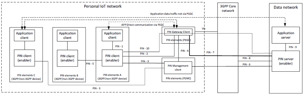
The PIN elements contains PIN client and/or application clients. The PIN Element with gateway capability (PEGC) performs the role of an entity supporting gateway capability for PIN. The PIN Element with management capability (PEMC) performs the role of an entity supporting management capability for PIN. A PIN includes at least one PEGC and at least one PEMC. The roles of UEs acting as PEGC and PEMC in 5GS are specified in clause 5.44 of TS 23.501.
The PIN enabler architecture consists of PIN client deployed in PIN element and PIN server deployed in Data network. The following interaction are supported in the PIN enabler architecture:
- The PIN client interacts with Application Client on the PINE over PIN-1 to provide and consume services in the PIN.
- The PIN server interacts with Application Server(s) over PIN-9. These interactions are supported using the CAPIF architecture as specified in TS 23.222.
- The PIN server interacts with 3GPP networks over PIN-8 to consume 3GPP network services.
- The PIN management client(s) interact with PIN server over PIN-6 for services related to management of PIN.
- The PIN client(s) interact with PIN server over PIN-10. These interactions traverse via the PEGC.
- The PIN gateway client(s) interact with PIN server over PIN-7.
- PIN client(s) interact with PIN gateway client over PIN-2.
- PIN management client interacts with PIN gateway client(s) over PIN-4.
- PIN management client interacts with PIN client(s) over PIN-3.
- A PIN client interacts with other PIN client(s) over PIN-5.
6.2.2 Architecture of user accessing services provided by PIN Element from outside the PIN p. 17
The Figure 6.2.2-1 shows the application architecture to enable authorized user to access services provided by PIN element behind the PEGC. For simplicity, not all functional elements of Figure 6.2.1-1 are shown in below Figure 6.2.2-1.
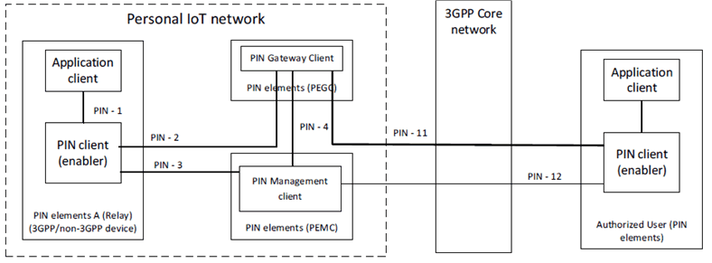
Figure 6.2.2-1: PINAPP architecture of User accessing services provided by PIN Element from outside the PIN
(⇒ copy of original 3GPP image)
(⇒ copy of original 3GPP image)
The interactions between PEGC and PIN client of the authorized user are supported over interface PIN-11. The interactions between PEMC and PIN client of the authorized user are supported over interface PIN-12. The authorized user uses PIN-12 to configure the policies in a PIN.
6.3 Functional entities p. 17
6.3.1 General p. 17
This clause describes the functional entities of the architecture for enabling personal IoT networks.
6.3.2 PIN client p. 18
The PIN enabler layer entity residing in the PIN elements that provides the client side functionalities required for application clients in order to consume the services offered by the PIN or to offer services for other PIN elements to consume.
It provides the following functionalities:
- Registration of the available service and capabilities;
- Service discovery of other PIN elements and application server;
- Communication with PIN clients of other PIN elements;
- Selection of relay for direct communication;
- Maintaining the PIN profile;
- Perform to join/leave a PIN;
- Support to discover the available PIN; and
- Support to receive the information to access the 5G core network via PEGC.
- Support service switch internal PIN.
- Support PIN service continuity of PEGC relocation or changing to 5GS communication.
6.3.3 PIN Management Client p. 18
A PIN Element with Management Capability is a PIN Element that provides a means for an authorized administrator to configure and manage a PIN.
It provides following functionalities:
- For a network operator or authorized user to configure the policies of the PIN;
- Provide life span information of the PIN to the authorized user or the PIN elements;
- Maintain the list of PIN elements who joined the PIN. Maintaining available PIN services;
- Maintain the PIN profile for each PIN and PINE in PIN;
-
To configure and manage a PIN, including:
- authorizing the PIN elements requesting to join the PIN;
- authorizing the PEGC and configure the parameters in PEGC to support PINE communication (via 5GS or direct communication);
- configuring PIN elements to enable discovery of services offered by other PIN Elements;
- add PIN elements to the PIN;
- configure PIN elements to enable direct communications;
- configure PIN elements to communicate with each other when gateway device is unavailable.
- support the PIN server endpoint address delivery to PIN elements;
- support the credentials delivery to PIN elements;
- Support service switch internal PIN.
- Support PIN service continuity of PEGC relocation or changing to 5GS communication.
6.3.4 PIN Gateway Client p. 19
A PIN Element with Gateway Capability is a PIN Element that has the ability to provide connectivity to a PINE for data and signaling exchange with PEMC, other PIN Elements or the DN. It may act as both the Layer-3 type relay which transparently forwards the traffic for PINE, and the application layer relay which terminates the PIN-2 reference points, processes the PIN management messages from/to the PINE, and performs authorization check.
It provides the following functionalities when acting as application layer relay:
- Maintain the PIN profile for each PIN and PINE in PIN;
- Maintain the access control information for each PIN and each PINE in PIN;
- Support to trigger the PDU session modification towards 5GS to request the resource for PIN;
- Enable the 5GS communication or direct communication;
- Support delivery of PIN server address;
- Support to deliver the credentials to PINE;
- Support PIN discovery function;
- Support service switch within the PIN.
- Support PIN service continuity of PEGC relocation or changing to 5GS communication.
- Receives the packet from the PINE and forwards the traffic to network transparently
- Receives the packet from the PINE and forwards the traffic transparently or another PINE transparently
- Receives the packet from the Network and forwards the packet towards to the PINE transparently
6.3.5 PIN server p. 19
A PIN server is deployed at network that provides server side functionalities required for managing the PIN.
It provides the following functionalities:
- Provisioning of configuration information to the PIN elements;
- Maintain the PIN profile for each PIN and PINE in PIN;
- PIN Management (Creation, modification and deletion) of PIN;
- Determine the access control information of PEGC/PINE in PIN;
- Authorization of the PINE to be added/removed into/from the PIN
- Support PIN discovery and application server discovery
- Support service switch internal PIN.
- Support PIN service continuity of PEGC relocation or changing to 5GS communication.
6.3.6 Application Client p. 19
An application client is the application resident in the PIN elements.
6.4 Reference Points p. 20
6.4.1 General p. 20
6.4.2 PIN-1 p. 20
The interactions related to enabling PINAPP, between the Application client and the PIN client.
6.4.3 PIN-2 p. 20
This reference point exists between PIN client and PEGC which connects PIN client of UE to PEGC. The PIN client uses this interface to communicate with other PIN clients within PIN or to access 3GPP network.
6.4.4 PIN-3 p. 20
This reference point exists between the PIN client and PEMC and following functionalities are supported over this reference point:
- Authorizing PIN clients to access PIN;
- Discovery of services offered by other PIN elements;
- Discovery and selection of PIN elements;
- Notifying the PIN information modification details (e.g. PEMC change, PEGC change, PIN capabilities change).
6.4.5 PIN-4 p. 20
This reference point exists between the PEGC and PEMC and following functionalities are supported over this reference point:
- Authorizing PEGC for PIN access;
- Notification of PIN elements joining or leaving the PIN by PEMC to PEGC;
- Delivery of PIN dynamic profile information by PEMC to PEGC whenever it changes;
6.4.6 PIN-5 p. 20
This reference point exists between the one PIN client and another PIN client and it supports direct connection over 3GPP or non-3GPP RAT. It also connects to PIN client of a PIN element to the PIN client of another PIN element.
6.4.7 PIN-6 p. 20
This reference point exists between the PEMC and PIN server and supports the following functionalities:
- Authorization of PEMC;
- Notifying PIN server whenever a PIN element joins or leaves the PIN, whenever a PIN client updates its capabilities;
- Notifying PIN server of PEGC replacement;
- Delivery of PIN dynamic profile information;
6.4.8 PIN-7 p. 21
This reference point exists between the PEGC and PIN server for the interactions related to enabling PINAPP
6.4.9 PIN-8 p. 21
This reference point exists between the PIN server and 3GPP core network for the interactions related to enabling PINAPP. It supports:
- UE's (PINE) location information retrieval as specified in clause 4.15.3 of TS 23.502.
6.4.10 PIN-9 p. 21
This reference point exists between the application server and PIN server for the interactions related to enabling PINAPP. This reference point is an instance of CAPIF-2/2e reference point as specified in TS 23.222.
6.4.11 PIN-10 p. 21
This reference point exists between the PIN client in PIN element and PIN server for the interactions related to enabling PINAPP.
6.4.12 PIN-11 p. 21
This reference point exists between the PEGC and PIN client from outside the PIN to access the services provided by PIN elements within the PIN.
PIN-11 utilizes Uu reference point as described in TS 23.501.
6.4.13 PIN-12 p. 21
This reference point exists between the PEMC and PIN client for configuring and managing the PIN from outside the PIN.
PIN-12 utilizes Uu reference point as described in TS 23.501.
6.5 Cardinality rules p. 21
6.5.1 Application Client (AC) p. 21
The following cardinality rules apply for application client:
- one or more application clients per PIN client.
6.5.2 PEMC p. 21
The following cardinality rules apply for PEMC:
- one or more PEMCs per PIN.
- Only one PEMC in certain PIN is assigned as primary role and other PEMCs if any are assigned with secondary role.
- One PEMC can act as PEMC for multiple PINs.
- One PEMC per UE.
6.5.3 PEGC p. 22
The following cardinality rules apply for PEGC:
- one or more PEGCs per PIN.
- For a certain PINE in PIN, one PEGC acts as default PEGC and other PEGCs act as backup.
- One PEGC can act as PEGC for multiple PINs.
- One PEGC per UE.
6.5.4 PIN server p. 22
The following cardinality rules apply for PIN server:
- one PIN server per PIN.
- Multiple PINs per PIN server.
6.5.5 PIN client p. 22
The following cardinality rules apply for PIN client:
- one or more PIN clients per PIN.
- one PIN client per PIN element.
- one PIN client per UE.
7 Identities and commonly used values p. 22
7.1 General p. 22
The following clauses list identities and commonly used values that are used in this technical specification.
7.2 Identities p. 22
7.2.1 General p. 22
The following clauses specify a collection of identities that are associated with entities defined and being used in this specification.
7.2.2 PIN ID p. 22
The PIN ID is a unique value in PLMN that identifies the PIN.
The PIN ID consists of two parts as follow:
- A string assigned by the PIN server which is unique for each PIN; and
- An identifier of PIN server (i.e. PIN server ID or domain name).
7.2.3 PIN server ID p. 22
The PIN server ID is a globally unique value that identifies the PIN server.
7.2.4 PIN client ID p. 23
The PIN client ID is a globally unique value that identifies the PIN client.
The PIN client ID is used for general identities for PINE, PEMC and PEGC.
For PEMC and PEGC, the PIN client ID may also be PEMC ID and PEGC ID.
For the PINE, the PIN client ID may also be PINE ID.
7.2.5 Application Client ID (ACID) p. 23
The ACID identifies the client side of a particular application, for e.g. SA6Video viewer, SA6MsgClient etc. For example, all SA6MsgClient clients will share the same ACID.
In case that the UE is running mobile OS, the ACID is a pair of OSId and OSAppId.
7.2.6 UE ID p. 23
The UE ID uniquely identifies a particular UE within a PLMN domain. Following identities are examples that can be used:
- GPSI, as defined in TS 23.501.
7.2.7 UE Location p. 23
The UE location identifies where the UE is connected to the network or the position of the UE. It provides consistent definition of the UE's location across the UE and network entities. Following values are examples of UE locations that can be used:
- Cell Identity, Tracking Area Identity, GPS Coordinates, Geographical/Geodetic Information, Current Location Retrieved, Age of Location Information, Current RAT Type or civic addresses as defined in clause 4.15.3 of TS 23.502 and TS 37.355.
![]()
![]()
![]()