Content for TS 23.501 Word version: 18.5.0
1…
3…
4.2.3
4.2.4
4.2.5…
4.2.8…
4.2.8.2.2
4.2.8.2.3…
4.2.8.4…
4.2.9…
4.2.15…
4.3…
4.3.3
4.3.4
4.3.5
4.4…
4.4.6…
4.4.8…
5…
5.3…
5.3.3…
5.4…
5.5…
5.6…
5.6.7…
5.7…
5.7.2…
5.7.3…
5.7.4
5.7.5…
5.8…
5.8.2.11…
5.9…
5.10…
5.11…
5.15…
5.15.11…
5.16…
5.17…
5.18…
5.19…
5.21…
5.22…
5.27…
5.28…
5.29…
5.30…
5.31…
5.32…
5.32.6…
5.33…
5.34…
5.35…
5.38…
5.43…
6…
6.3…
6.3.8…
7…
7.2…
8…
8.2.4
8.2.5…
8.3…
A…
D…
E…
F
G…
G.3
G.4…
H…
J
K…
M…
N…
O…
P…
F Redundant user plane paths based on multiple UEs per device |R16| p. 620
This clause describes an approach to realize multiple user plane paths in the system based on a device having multiple UEs and specific network deployments.
The approach assumes a RAN deployment where redundant coverage by multiple gNBs (in the case of NR) is generally available. Upper layer protocols, such as the IEEE 802.1 TSN (Time Sensitive Networking), can make use of the multiple user plane paths.
The UEs belonging to the same terminal device request the establishment of PDU Sessions that use independent RAN and CN network resources using the mechanisms outlined below.
This deployment option has a number of preconditions:
- The redundancy framework uses separate gNBs to achieve user plane redundancy over the 3GPP system. It is however up to operator deployment and configuration whether separate gNBs are available and used. If separate gNBs are not available for a device, the redundancy framework may still be applied to provide user plane redundancy in the rest of the network as well as between the device and the gNB using multiple UEs.
- Terminal devices integrate multiple UEs which can connect to different gNBs independently.
- RAN coverage is redundant in the target area: it is possible to connect to multiple gNBs from the same location. To ensure that the two UEs connect to different gNBs, the gNBs need to operate such that the selection of gNBs can be distinct from each other (e.g. gNB frequency allocation allows the UE to connect to multiple gNBs).
- The core network UPF deployment is aligned with RAN deployment and supports redundant user plane paths.
- The underlying transport topology is aligned with the RAN and UPF deployment and supports redundant user plane paths.
- The physical network topology and geographical distribution of functions also supports the redundant user plane paths to the extent deemed necessary by the operator.
- The operation of the redundant user plane paths is made sufficiently independent, to the extent deemed necessary by the operator, e.g. independent power supplies.

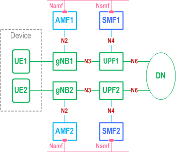
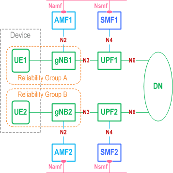
The approach comprises the following main components shown as example using NR in Figure F-2.
- gNB selection: The selection of different gNBs for the UEs in the same device is realized by the concept of UE Reliability Groups for the UEs and also for the cells of gNBs. By grouping the UEs in the device and cells of gNBs in the network into more than one reliability group and preferably selecting cells in the same reliability group as the UE, it is ensured that UEs in the same device can be assigned different gNBs for redundancy as illustrated in Figure F-2, where UE1 and the cells of gNB1 belong to reliability group A, and UE2 and the cells of gNB2 belong to reliability group B.

For determining the reliability grouping of a UE, one of the following methods or a combination of them can be used:
- It could be configured explicitly to the UE and sent in a Registration Request message to the network using an existing parameter (such as an S-NSSAI in the Requested NSSAI where the SST is URLLC; the Reliability Group can be decided by the SD part).
- It could also be derived from existing system parameters (e.g. SUPI, PEI, S-NSSAI, RFSP) based on operator configuration.
- UPF selection: UPF selection mechanisms as described in clause 6.3.3 can be used to select different UPFs for the UEs within the device. The selection may be based either on UE configuration or network configuration of different DNNs leading to the same DN, or different slices for the two UEs. It is possible to use the UE's Reliability Group, described above for gNB selection, as an input to the UPF selection. The proper operator configuration of the UPF selection can ensure that the path of the PDU Sessions of UE1 and UE2 are independent.
-
Control plane: The approach can optionally apply different control plane entities for the individual UEs within the device. This may be achieved by using:
- different DNNs for the individual UEs within the device to select different SMFs,
- or applying different slices for the individual UEs within the device either based on UE configuration or network subscription, to select different AMFs and/or SMFs.