Content for TS 37.113 Word version: 17.0.0
1 Scope
2 References
3 Definitions, symbols and abbreviations
3.1 Definitions
3.2 Symbols
3.3 Abbreviations
...
...
1 Scope p. 7
The present document covers the assessment of NR, E-UTRA, UTRA, GSM/EDGE and NB-IoT Multi-Standard Radio (MSR) Base Stations and associated ancillary equipment in respect of Electromagnetic Compatibility (EMC).
The present document specifies the applicable test conditions, performance assessment and performance criteria for NR, E-UTRA, UTRA, GSM/EDGE and NB-IoT Base Stations and associated ancillary equipment in one of the following categories:
- Multi-Standard Radio (MSR) Base Stations for NR, E-UTRA, UTRA and GSM/EDGE meeting the requirements of TS 37.104, with conformance demonstrated by compliance to TS 37.141.
- BS type 1-C for NR meeting the requirements of TS 38.104, with conformance demonstrated by compliance to TS 38.141-1
- Base Stations for E-UTRA meeting the requirements of TS 36.104, with conformance demonstrated by compliance to TS 36.141.
- Base Stations for UTRA FDD meeting the requirements of TS 25.104, with conformance demonstrated by compliance to TS 25.141.
- Base Stations for UTRA TDD meeting the requirements of TS 25.105, with conformance demonstrated by compliance to TS 25.142.
- Base Stations for GSM/EDGE meeting the requirements of TS 45.005, with conformance demonstrated by compliance to TS 51.021.
- Base Stations for NB-IoT meeting the requirements of TS 36.104, with conformance demonstrated by compliance to TS 36.141.
2 References p. 7
The following documents contain provisions which, through reference in this text, constitute provisions of the present document.
- References are either specific (identified by date of publication, edition number, version number, etc.) or non-specific.
- For a specific reference, subsequent revisions do not apply.
- For a non-specific reference, the latest version applies. In the case of a reference to a 3GPP document (including a GSM document), a non-specific reference implicitly refers to the latest version of that document in the same Release as the present document.
[1]
TR 21.905: "Vocabulary for 3GPP Specifications".
[2]
TS 25.104: "Base Station (BS) radio transmission and reception (FDD)".
[3]
TS 25.105: "Base Station (BS) radio transmission and reception (TDD)".
[4]
TS 36.104: "Evolved Universal Terrestrial Radio Access (E-UTRA); Base Station (BS) radio transmission and reception ".
[5]
TS 45.005: "Radio transmission and reception".
[6]
TS 37.104: "NR, E-UTRA, UTRA and GSM/EDGE; Multi-Standard Radio (MSR) Base Station (BS) radio transmission and reception".
[7]
TS 25.141: "Base Station (BS) conformance testing (FDD)".
[8]
TS 25.142: "Base Station (BS) conformance testing (TDD)".
[9]
TS 36.141: "Evolved Universal Terrestrial Radio Access (E-UTRA); Base Station (BS) conformance testing".
[10]
TS 51.021: "Base Station System (BSS) equipment specification; Radio aspects".
[11]
TS 37.141: "NR, E-UTRA, UTRA and GSM/EDGE; Multi-Standard Radio (MSR) Base Station (BS) conformance testing".
[12]
IEC 61000-6-1: 2005: "Electromagnetic compatibility (EMC) - Part 6-1: Generic standards - Immunity for residential, commercial and light-industrial environments".
[13]
IEC 61000-6-3: 2006/AMD1:2010: "Electromagnetic compatibility (EMC) - Part 6-3: Generic standards - Emission standard for residential, commercial and light-industrial environments".
[14]
IEC 60050-161: "International Electrotechnical Vocabulary (IEV) - Part 161: Electromagnetic compatibility".
[15]
ITU-R Recommendation SM.329: "Unwanted emissions in the spurious domain".
[16]
ITU-R Recommendation SM.1539-1 (2001): "Variation of the boundary between the out-of-band and spurious domains required for the application of Recommendations ITU-R SM.1541 and ITU-R SM.329".
[17] Void
[18] Void
[19]
IEC 61000-3-2 (2004): "Electromagnetic compatibility (EMC) - Part 3-2: Limits - Limits for harmonic current emissions (equipment input current ≤ 16 A)".
[20]
IEC 61000-3-12 (2005): "Electromagnetic compatibility (EMC) - Part 3-12: Limits - Limits for harmonic current produced by equipment connected to public low-voltage system with input current >16 A and ≤ 75 A".
[21]
IEC 61000-3-3 (2002): "Electromagnetic compatibility (EMC) - Part 3-3: Limits - Limitation of voltage fluctuations and flicker in low-voltage supply systems for equipment with rated current ≤ 16 A".
[22]
IEC 61000-3-11 (2000): "Electromagnetic compatibility (EMC) - Part 3-11: Limits - Limitation of voltage fluctuations and flicker in low-voltage supply systems for equipment with rated current ≤ 75 A and subject to conditional connections".
[23]
IEC 61000-4-3: "Electromagnetic compatibility (EMC) - Part 4-3: Testing and measurement techniques - Radiated, radio-frequency electromagnetic field immunity test".
[24]
IEC 61000-4-2: "Electromagnetic compatibility (EMC) - Part 4-2: Testing and measurement techniques - Electrostatic discharge immunity test".
[25]
IEC 61000-4-4: "Electromagnetic compatibility (EMC) - Part 4-4: Testing and measurement techniques - Electrical fast transient/burst immunity test".
[26]
IEC 61000-4-6: "Electromagnetic compatibility (EMC) - Part 4-6: Testing and measurement techniques - Immunity to contacted disturbances, induced by radio frequency fields".
[27]
IEC 61000-4-11: "Electromagnetic compatibility (EMC) - Part 4-11: Testing and measurement techniques - Voltage dips, short interruptions and voltage variations. Immunity tests".
[28]
IEC 61000-4-5: "Electromagnetic compatibility (EMC) - Part 4-5: Testing and measurement techniques - Surge immunity test".
[29]
TS 25.101: "User Equipment (UE) radio transmission and reception (FDD)".
[30]
TS 25.102: "User Equipment (UE) radio transmission and reception (TDD)".
[31]
TS 36.101: "Evolved Universal Terrestrial Radio Access (E-UTRA); User Equipment (UE) radio transmission and reception".
[32]
TS 45.008: "Radio subsystem link control".
[33]
TS 51.010-1: " Mobile Station (MS) conformance specification; Part 1: Conformance specification".
[34]
CISPR 32: "Electromagnetic compatibility of multimedia equipment - Emission requirements".
[35]
TS 38.104: "NR; Base Station (BS) radio transmission and reception".
[36]
TS 38.141-1: "NR; Base Station (BS) conformance testing; Part 1: Conducted conformance testing".
[37]
TS 38.141-2: "NR; Base Station (BS) conformance testing; Part 2: Radiated conformance testing".
[38]
TS 38.101-4: "NR; User Equipment (UE) radio transmission and reception; Part 4: Performance requirements".
[39]
TS 37.114: "Active Antenna System (AAS) Base Station (BS), Electromagnetic Compatibility (EMC)".
[40]
IEC 61000-4-21: "Electromagnetic Compatibility (EMC) Part 4-21: Testing And Measurement Techniques Reverberation Chamber Test Methods".
3 Definitions, symbols and abbreviations p. 9
3.1 Definitions p. 9
For the purposes of the present document, the terms and definitions given in TR 21.905 and the following apply. A term defined in the present document takes precedence over the definition of the same term, if any, in TR 21.905.
Ancillary equipment:
Equipment (apparatus), used in connection with a receiver, transmitter or transceiver is considered as an ancillary equipment (apparatus) if:
- the equipment is intended for use in conjunction with a receiver, transmitter or transceiver to provide additional operational and/or control features to the radio equipment, (e.g. to extend control to another position or location); and
- the equipment cannot be used on a stand-alone basis to provide user functions independently of a receiver, transmitter or transceiver; and
- the receiver, transmitter or transceiver to which it is connected, is capable of providing some intended operation such as transmitting and/or receiving without the ancillary equipment (i.e. it is not a sub-unit of the main equipment essential to the main equipment basic functions).
connector at the conducted interface of the BS type 1-C
Band category:
group of operating bands for which the same MSR scenarios apply
Base Station equipment:
Radio and/or ancillary equipment intended for operation at a fixed location and powered directly or indirectly (e.g. via an AC/DC converter or power supply) by AC mains network, or an extended local DC mains network.
Base Station RF bandwidth:
The bandwidth in which a Base Station transmits and/or receives multiple carriers and/or RATs simultaneously.
Base Station RF bandwidth edge:
The frequency of one of the edges of the Base Station RF bandwidth.
BS type 1-C:
NR base station operating at FR1 with requirements set consisting only of conducted requirements defined at individual antenna connectors.
Channel bandwidth:
The RF bandwidth supporting a single E-UTRA RF carrier with the transmission bandwidth configured in the uplink or downlink of a cell. The channel bandwidth is measured in MHz and is used as a reference for transmitter and receiver RF requirements.
Continuous phenomena (continuous disturbance):
Electromagnetic disturbance, the effects of which on a particular device or equipment cannot be resolved into a succession of distinct effects (IEC 60050-161 [14]).
Lower RF bandwidth edge:
The frequency of the lower edge of the Base Station RF bandwidth, used as a frequency reference point for transmitter and receiver requirements.
Maximum Base Station RF bandwidth:
The maximum RF bandwidth supported by a BS within an operating band.
Maximum throughput:
The maximum achievable throughput for a reference measurement channel.
MB-MSR Base Station:
MSR Base Station characterized by the ability of its transmitter and/or receiver to process two or more carriers in common active RF components simultaneously, where at least one carrier is configured at a different non-overlapping operating band than the other carrier(s).
MSR Base station:
Base Station characterized by the ability of its receiver and transmitter to process two or more carriers in common active RF components simultaneously in a declared RF bandwidth, where at least one carrier is of a different RAT than the other carrier(s).
NB-IoT In-band operation:
NB-IoT is operating in-band when it utilizes the resource block(s) within a normal E-UTRA carrier.
NB-IoT guard band operation:
NB-IoT is operating in guard band when it utilizes the unused resource block(s) within an E-UTRA carrier's guard-band.
NB-IoT standalone operation:
NB-IoT is operating standalone when it utilizes its own spectrum, for example the spectrum currently being used by GERAN systems as a replacement of one or more GSM carriers, as well as scattered spectrum for potential IoT deployment.
Radio communications equipment:
Telecommunications equipment which includes one or more transmitters and/or receivers and/or parts thereof for use in a fixed, mobile or portable application. It can be operated with ancillary equipment but if so, is not dependent on it for basic functionality.
Radio equipment:
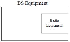
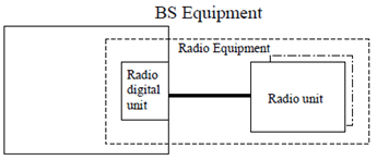
Equipment which contains Radio digital unit and Radio unit.
Radio digital unit:
Equipment which contains base band and functionality for controlling Radio unit.
Radio unit:
Equipment which contains transmitter and/or receiver.
Port:
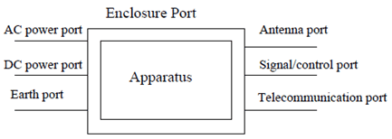
A particular interface, of the specified equipment (apparatus), with the electromagnetic environment. For example, any connection point on an equipment intended for connection of cables to or from that equipment is considered as a port (see figure 3.1.1).
Receiver exclusion band:
The receiver exclusion band is the band of frequencies over which no tests of radiated immunity of a receiver are made. The exclusion band for receivers is expressed relative to the base station receive band.
Signal and control port:
Port which carries information or control signals, excluding antenna ports.
Telecommunication port:
Ports which are intended to be connected to telecommunication networks (e.g. public switched telecommunication networks, integrated services digital networks), local area networks (e.g. Ethernet, Token Ring) and similar networks.
Throughput:
The number of payload bits successfully received per second for a reference measurement channel in a specified reference condition.
Transient phenomena:
Pertaining to or designating a phenomena or a quantity which varies between two consecutive steady states during a time interval short compared with the time-scale of interest (IEC 60050-161 [14]).
Transmitter exclusion band:
The transmitter exclusion band is the band of frequencies over which no tests of radiated immunity of a transmitter are made. The exclusion band for transmitters is expressed relative to the carrier frequencies used (the carrier frequencies of the base stations activated transmitter(s)).
Upper RF bandwidth edge:
The frequency of the upper edge of the Base Station RF bandwidth, used as a frequency reference point for transmitter and receiver requirements.


3.2 Symbols p. 12
For the purposes of the present document, the following symbols apply:
BWChannel
Channel bandwidth
FC,high
Center frequency of the highest transmitted/received carrier.
FC,low
Center frequency of the lowest transmitted/received carrier.
FDL_high
The highest frequency of the downlink operating band
FDL_low
The lowest frequency of the downlink operating band
foffset
Frequency offset used for discovering narrowband response for receivers
Foffset, RAT
Frequency offset from FC,high to the upper RF bandwidth edge or FC,low to the lower RF bandwidth edge for a specific RAT
FUL_high
The highest frequency of the uplink operating band
FUL_low
The lowest frequency of the uplink operating band
ΔfOBUE
Maximum offset of the operating band unwanted emissions mask from the operating band edge
ΔfOOB
Maximum offset of the out-of-band boundary from the uplink operating band edge
3.3 Abbreviations p. 12
For the purposes of the present document, the abbreviations given in TR 21.905 and the following apply. An abbreviation defined in the present document takes precedence over the definition of the same abbreviation, if any, in TR 21.905.
AC
Alternating Current
AMN
Artificial Mains Network
ARFCN
Absolute Radio Frequency Channel Number
BC
Band Category
BER
Bit Error Ratio
BLER
Block Error Ratio
CDN
Coupling/Decoupling Network
CS
Capability Set
DC
Direct Current
E-UTRA
Evolved Universal Terrestrial Radio Access
EARFCN
E-UTRA Absolute Radio Frequency Channel Number
EMC
Electromagnetic Compatibility
EPC
Evolved Packet Core
ESD
Electrostatic discharge
EUT
Equipment Under Test
FR
Frequency Range
FRC
Fixed Reference Channel
MB-MSR
Multi-Band Multi-Standard Radio
MSR
Multi-Standard Radio
NB-IoT
Narrowband - Internet of Things
NR
New Radio
NR-ARFCN
NR Absolute Radio Frequency Channel Number
NTC
Test Configuration for Non-contiguous operation
RAT
Radio Access Technology
RF
Radio frequency
rms
root mean square
TC
Test Configuration
UARFCN
UTRA Absolute Radio Frequency Channel Number
UTRA
Universal Terrestrial Radio Access