Content for TS 23.246 Word version: 17.0.0
4 MBMS Architecture
4.1 Overview
4.2 Reference Architecture Model
4.2.1 GPRS
4.2.2 EPS
4.3 MBMS Specific Reference points
4.3.1 Gmb
4.3.1a SGmb
4.3.2 Mz
4.3.3 Reference Points for Evolved Packet System
...
...
4 MBMS Architecture p. 9
4.1 Overview p. 9
MBMS is a point-to-multipoint service in which data is transmitted from a single source entity to multiple recipients. Transmitting the same data to multiple recipients allows network resources to be shared.
The MBMS bearer service offers two modes:
- Broadcast Mode;
- Multicast Mode.
- managing the MBMS bearer service activation status of UEs (in the case of multicast mode);
- outsourcing authorisation decisions to the MBMS User Service (i.e. to the BM-SC) (in the case of multicast mode);
- providing control of session initiation/modification/termination by the MBMS User Service and managing bearer resources for the distribution of MBMS data (in the case or multicast and broadcast modes).
4.2 Reference Architecture Model p. 10
4.2.1 GPRS |R9| p. 10

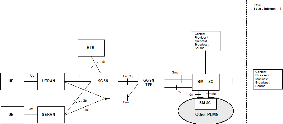
Figure 1a: Reference architecture for GPRS to support the MBMS bearer service with GERAN and UTRAN
(⇒ copy of original 3GPP image)
(⇒ copy of original 3GPP image)
4.2.2 EPS |R9| p. 10

Figure 1b: Reference architecture for Evolved Packet System with E-UTRAN and UTRAN (MBMS Broadcast Mode only)
(⇒ copy of original 3GPP image)
(⇒ copy of original 3GPP image)
4.3 MBMS Specific Reference points p. 11
4.3.1 Gmb p. 11
Signalling between GGSN and BM-SC is exchanged at Gmb reference point. This represents the network side boundary of the MBMS Bearer Service from a control plane perspective. This includes user specific Gmb signalling and MBMS bearer service specific signalling.
MBMS bearer service specific Gmb signalling:
- The GGSN establishes the MBMS bearer context and registers at BM-SC.
- The GGSN or the BM-SC releases the MBMS bearer context and de-registers the GGSN from the BM-SC.
- The BM-SC indicates session start, update and stop to the GGSN including session attributes like QoS and MBMS service area.
- The BM-SC authorises the user specific MBMS multicast service activation (join) at the GGSN.
- The GGSN reports to the BM-SC the successful user specific MBMS multicast activation (join) to allow the BM-SC to synchronise the BM-SC MBMS UE context with the MBMS UE contexts in the SGSN and GGSN.
- The GGSN reports to the BM-SC when a user specific MBMS multicast service is released or deactivated (e.g. at implicit detach). The GGSN makes this report in order to synchronise the BM-SC MBMS UE context with the MBMS UE contexts in the SGSN and GGSN.
4.3.1a SGmb |R9| p. 11
The SGmb reference point has similar functions with the Gmb interface in control plane except for the Multicast Mode related functions. Specifically,
MBMS bearer service specific SGmb signalling:
- The BM-SC indicates session start, update and stop to the MBMS-GW including session attributes like QoS and MBMS service area, and some of attributes may be different from them in Gmb.
4.3.2 Mz |R7| p. 11
Mz is the roaming variant of the Gmb reference point with the same functionality as described under Gmb, i.e. with MBMS bearer and User specific signalling.
MBMS bearer and User specific Mz signalling is used between a BM-SC in the visited PLMN and a BM-SC in the home PLMN when MBMS services from the home PLMN are offered by the visited PLMN.
User specific signalling is used between a BM-SC in the visited PLMN and a BM-SC in the home PLMN when the visited PLMN offers MBMS user services to roaming users. This user specific Mz signalling provides home PLMN authorisation for MBMS user services that are provided by the visited PLMN. This mechanism supports only MBMS user service classes that are offered by the visited and by the home PLMN.
Mz may use proxying capabilities as described for Gmb, e.g. to proxy signalling between BM-SCs. An APN may be included in the signalling between BM-SCs, which is used to select an appropriate GGSN to access the MBMS service aiming for an optimized routing, resource saving, or operator policy.
4.3.3 Reference Points for Evolved Packet System |R9| p. 12
M1:
It is the reference point between MBMS GW and E-UTRAN/UTRAN for MBMS data delivery. IP Multicast is used on this interface to forward data.
M3:
It is the reference point for the control plane between MME and E-UTRAN.
Sm:
It is the reference point for the control plane between MME and MBMS GW.
Sn:
It is the reference point between MBMS GW and SGSN (S4 based) for the control plane and for MBMS data delivery. Point-to-point mode is used on this interface to forward data..
SGi-mb:
It is the reference point between BM-SC and MBMS GW function for MBMS data delivery.
SGmb:
It is the reference point for the control plane between BM-SC and MBMS GW.
Protocol assumption:
- The Sm reference point is based on GTPv2-C.
- The Sn reference point is based on GTPv2-C and GTPv1-U.
- The M1 reference point is based on GTPv1-U.