Content for TS 23.060 Word version: 18.0.0
1…
5…
5.3.8…
5.4…
5.4.2…
5.4.9…
5.6…
5.6.2
5.6.3…
5.6.3.7…
5.7…
6…
6.3…
6.5…
6.6…
6.8…
6.9…
6.9.1.3
6.9.2…
6.9.2.2…
6.9.2.2.2
6.9.2.2.3…
6.9.2.2.5…
6.9.3…
6.10…
6.12…
6.13…
6.13.1.2…
6.13.2…
6.13.2.2
6.14…
8…
8.2
9…
9.2.2…
9.2.2.2
9.2.2.3…
9.2.3…
9.2.3.2…
9.2.3.3…
9.2.4…
9.2.4.2…
9.2.5…
12…
12.5…
12.6…
12.7…
12.8…
13…
14…
15…
15.3…
16…
16.2…
A…
B…
6.13.2.2 A/Gb mode to Iu mode Inter-SGSN Change p. 197
6.13.2.2.1 A/Gb mode to Iu mode Inter-SGSN Change using Gn/Gp |R8| p. 197
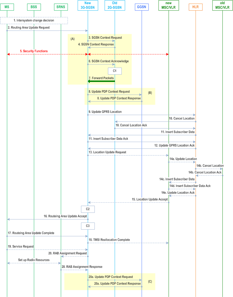
The inter-system change from A/Gb mode to Iu mode takes place when a GPRS-attached MS changes from A/Gb mode to UTRAN or GERAN Iu mode and the new RAN node serving the MS is served by a different SGSN. In this case the RA changes. Therefore, the MS shall initiate a Iu mode RA update procedure by establishing an RRC connection and initiating the RA update procedure. The RA update procedure is either combined RA / LA update or only RA update, these RA update cases are illustrated in Figure 55. In the context of this specification, the terms RNS or RNC refer also to a GERAN BSS or BSC (respectively) when serving an MS in Iu mode.
If the network operates in mode I, then an MS, that is both PS-attached and CS-attached, shall perform the Combined RA / LA Update procedures. This concerns only idle mode (see TS 23.122), as no combined RA / LA updates are performed during a CS connection.
Step 1.
If the new SGSN is unable to update the PDP context in one or more GGSNs, the new SGSN shall deactivate the corresponding PDP contexts as described in clause "SGSN-initiated PDP Context Deactivation Procedure". This shall not cause the SGSN to reject the routeing area update.
The PDP Contexts shall be sent from old to new SGSN in a prioritized order, i.e. the most important PDP Context first in the SGSN Context Response message. (The prioritization method is implementation dependent, but should be based on the current activity).
The new SGSN shall determine the Maximum APN restriction based on the received APN Restriction of each PDP context from the GGSN and then store the new Maximum APN restriction value.
If the new SGSN is unable to support the same number of active PDP contexts as received from old SGSN, the new SGSN should use the prioritisation sent by old SGSN as input when deciding which PDP contexts to maintain active and which ones to delete. In any case, the new SGSN shall first update all contexts in one or more GGSNs and then deactivate the context(s) that it cannot maintain as described in clause "SGSN-initiated PDP Context Deactivation Procedure". This shall not cause the SGSN to reject the routeing area update.
The CAMEL procedure calls shall be performed, see referenced procedures in TS 23.078:
The MS or RAN decides to perform an inter-system change, which makes the MS switch to a new cell where Iu mode has to be used, and stops transmission to the network.
Step 2.
The MS sends a Routeing Area Update Request (P-TMSI, old RAI, old P-TMSI Signature, Update Type, CM, MS Network Capability, Voice domain preference and UE's usage setting) message to the new 3G SGSN. Update Type shall indicate RA update or combined RA / LA update, or, if the MS wants to perform an IMSI attach, combined RA / LA update with IMSI attach requested, and also if the MS has a follow-on request, i.e. if there is pending uplink traffic (signalling or data). The SGSN may use, as an implementation option, the follow-on request indication to release or keep the Iu connection after the completion of the RA update procedure. The SRNC shall add the Routeing Area Identity before forwarding the message to the 3G SGSN. This RA identity corresponds to the RAI in the MM system information sent by the SRNC to the MS. The UE sets the voice domain preference and UE's usage setting according to its configuration, as described in clause 5.3.15.
Step 3.
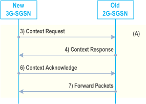
The new 3G SGSN uses the old RAI received from the MS to derive the old 2G SGSN address, and sends an SGSN Context Request (old RAI, old P-TMSI, New SGSN Address) message to the old 2G SGSN to get the MM and PDP contexts for the MS. If the new SGSN provides functionality for Intra Domain Connection of RAN Nodes to Multiple CN Nodes, the new SGSN may derive the old SGSN from the old RAI and the old P-TMSI and send the SGSN Context Request message to this old SGSN. Otherwise, the new SGSN derives the old SGSN from the old RAI. In any case the new SGSN will derive an SGSN that it believes is the old SGSN. This derived SGSN is itself the old SGSN, or it is associated with the same pool area as the actual old SGSN and it will determine the correct old SGSN from the P-TMSI and relay the message to that actual old SGSN. The old 2G-SGSN validates the old P-TMSI Signature and responds with an appropriate error cause if it does not match the value stored in the old 2G SGSN. If the received old P-TMSI Signature does not match the stored value, the old 2G-SGSN should initiate the security functions in the new 3G-SGSN. If the security functions authenticate the MS correctly, the new 3G-SGSN shall send an SGSN Context Request (old RAI, IMSI, MS Validated, New SGSN Address) message to the old 2G-SGSN. MS Validated indicates that the new 3G-SGSN has authenticated the MS. If the old P-TMSI Signature was valid or if the new 3G-SGSN indicates that it has authenticated the MS correctly, the old 2G SGSN starts a timer and stops the transmission of N PDUs to the MS.
Step 4.
The old 2G SGSN responds with an SGSN Context Response (MM Context, PDP Contexts, Negotiated Evolved ARP) message. Each PDP Context includes the GTP sequence number for the next downlink N PDU to be sent to the MS and the GTP sequence number for the next uplink N PDU to be tunnelled to the GGSN. Each PDP Context also includes the SNDCP Send N PDU Number for the next downlink N PDU to be sent in acknowledged mode SNDCP to the MS and the SNDCP Receive N PDU Number for the next uplink N PDU to be received in acknowledged mode SNDCP from the MS. The new 3G-SGSN derives the corresponding PDCP sequence numbers from these N PDU sequence numbers by adding eight most significant bits "1". These PDCP sequence numbers are stored in the 3G-SGSN PDP contexts. The new 3G-SGSN shall ignore the MS Network Capability contained in MM Context of SGSN Context Response only when it has previously received an MS Network Capability in the Routeing Area Request.
Step 5.
Security functions may be executed. If the SGSN Context Response message did not include IMEISV and the ADD function is supported by the new 3G-SGSN, then the IMEISV shall be retrieved from the MS.
Step 6.
The new 3G SGSN sends an SGSN Context Acknowledge message to the old 2G SGSN. This informs the old 2G SGSN that the new 3G SGSN is ready to receive data packets belonging to the activated PDP contexts. The old SGSN marks in its context that the MSC/VLR association and the information in the GGSNs and the HLR are invalid. This triggers the MSC/VLR, the GGSNs, and the HLR to be updated if the MS initiates a routeing area update procedure back to the old SGSN before completing the ongoing routeing area update procedure.
Step 7.
The old 2G SGSN duplicates the buffered N PDUs and starts tunnelling them to the new 3G SGSN. Additional N PDUs received from the GGSN before the timer described in step 3 expires are also duplicated and tunnelled to the new 3G SGSN. N-PDUs that were already sent to the MS in acknowledged mode SNDCP and that are not yet acknowledged by the MS are tunnelled together with their related SNDCP N-PDU sequence number. No PDCP sequence numbers shall be indicated for these N-PDUs. No N PDUs shall be forwarded to the new 3G SGSN after expiry of the timer described in step 3.
Step 8.
The new 3G SGSN sends an Update PDP Context Request (new SGSN Address, TEID, QoS Negotiated, Negotiated Evolved ARP, serving network identity, CN Operator Selection Entity, CGI/SAI, User CSG Information, RAT type, MS Info Change Reporting support indication, NRSN) message to each GGSN concerned. The SGSN shall send the serving network identity and the CN Operator Selection Entity to the GGSN. The CN Operator Selection Entity indicates whether the Serving Network has been selected by the UE or by the network. NRSN indicates SGSN support of the network requested bearer control. The inclusion of the Negotiated Evolved ARP IE indicates that the SGSN supports the Evolved ARP feature. If the new SGSN did not receive a Negotiated Evolved ARP IE in the SGSN Context Response message from the old SGSN then the new SGSN shall derive this value from the Allocation/Retention Priority of the QoS profile negotiated according to Annex E of TS 23.401. Each GGSN updates its PDP context fields and returns an Update PDP Context Response (TEID, Prohibit Payload Compression, APN Restriction, MS Info Change Reporting Action, CSG Information Reporting Action, BCM, Negotiated Evolved ARP) message. The GGSN sets the Negotiated Evolved ARP based on local policy or PCC. The Allocation/Retention Priority of the QoS Profile Negotiated is derived from the Evolved ARP according to the mapping principles of TS 23.401, Annex E. The Prohibit Payload Compression indicates that the SGSN should negotiate no data compression for this PDP context. The SGSN shall apply the Negotiated Evolved ARP if received from the GGSN.
Step 9.
The new 3G SGSN informs the HLR of the change of SGSN by sending an Update GPRS Location (SGSN Number, SGSN Address, IMSI, IMEISV, Homogenous Support of IMS Voice over PS Sessions) message to the HLR. IMEISV is sent if the ADD function is supported. For "Homogenous Support of IMS Voice over PS Sessions", see clause 5.3.8A.
Step 10.
The HLR sends a Cancel Location (IMSI, Cancellation Type) message to the old 2G SGSN. The old 2G SGSN removes the MM and PDP contexts if the timer described in step 3 is not running. If the timer is running, the MM and PDP contexts are removed when the timer expires. The old 2G SGSN acknowledges with a Cancel Location Ack (IMSI) message.
Step 11.
The HLR sends an Insert Subscriber Data (IMSI, Subscription Data) message to the new 3G SGSN. The 3G SGSN constructs an MM context for the MS and returns an Insert Subscriber Data Ack (IMSI) message to the HLR. If the S6d interface is used between S4-SGSN and HSS the messages "Insert Subscriber Data" and "Insert Subscriber Data Ack" are not used. Instead the Subscription Data is sent by HSS in the message Update Location Ack (Step 15).
Step 12.
The HLR acknowledges the Update GPRS Location by returning an Update GPRS Location Ack (IMSI, GPRS Subscriber Data (only if S6d interface is used)) message to the new 3G SGSN.
Step 13.
If the association has to be established, if Update Type indicates combined RA / LA update with IMSI attach requested, or if the LA changed with the routeing area update, the new SGSN sends a Location Update Request (new LAI, IMSI, SGSN Number, Location Update Type) to the VLR. Location Update Type shall indicate IMSI attach if Update Type in step 1 indicated combined RA / LA update with IMSI attach requested. Otherwise, Location Update Type shall indicate normal location update. When the SGSN does not provide functionality for the Intra Domain Connection of RAN Nodes to Multiple CN Nodes, the VLR number is derived from the RAI. When the SGSN provides functionality for Intra Domain Connection of RAN Nodes to Multiple CN Nodes, the SGSN uses the RAI and a hash value from the IMSI to determine the VLR number. The 3G SGSN starts the location update procedure towards the new MSC/VLR upon receipt of the first Insert Subscriber Data message from the HLR in step 12). The VLR creates or updates the association with the 3G SGSN by storing SGSN Number. In networks that support network sharing, the Location Update Request includes the identity of the selected core network operator if the new 3G-SGSN has received this information from the RNS, as described in TS 23.251.
Step 14.
If the subscriber data in the VLR is marked as not confirmed by the HLR, the new VLR informs the HLR. The HLR cancels the old VLR and inserts subscriber data in the new VLR:
Step 15.
- The new VLR sends an Update Location (new VLR) to the HLR.
- The HLR cancels the data in the old VLR by sending Cancel Location (IMSI) to the old VLR.
- The old VLR acknowledges with Cancel Location Ack (IMSI).
- The HLR sends Insert Subscriber Data (IMSI, subscriber data) to the new VLR.
- The new VLR acknowledges with Insert Subscriber Data Ack (IMSI).
- The HLR responds with Update Location Ack (IMSI) to the new VLR.
The new VLR allocates a new TMSI and responds with Location Update Accept (VLR TMSI) to the 3G SGSN. VLR TMSI is optional if the VLR has not changed.
Step 16.
The new 3G SGSN validate the MS's presence in the new RA. If due to roaming restrictions or access restrictions the MS is not allowed to be attached in the RA, or if subscription checking fails, the new 3G SGSN rejects the routeing area update with an appropriate cause. If the network supports the MOCN configuration for network sharing, the SGSN may, if the MS is not a 'Network Sharing Supporting MS', in this case decide to initiate redirection by sending a Reroute Command to the RNS, as described in TS 23.251 instead of rejecting the routeing area update. If all checks are successful, the new 3G SGSN constructs MM and PDP contexts for the MS. The new 3G SGSN responds to the MS with a Routeing Area Update Accept (P-TMSI, P-TMSI signature, IMS voice over PS Session Supported Indication, Emergency Service Support) message. The IMS voice over PS Session Supported Indication is set as described in clause 5.3.8.
The Emergency Service Support indicator shall be included when going to UTRAN to inform the MS that Emergency PDP contexts are supported, i.e. the MS is allowed to request activation of emergency PDP context when needed.
If after step 8 the new SGSN receives a Downlink Data Notification message or any other downlink signalling message while the MS is still connected, the new SGSN may prolong the PS signalling connection with the MS.
Step 17.
The MS acknowledges the new P-TMSI by returning a Routeing Area Update Complete message to the SGSN.
Step 18.
The new 3G SGSN sends TMSI Reallocation Complete message to the new VLR, if the MS confirms the VLR TMSI.
Step 19.
If the MS has uplink data or signalling pending it shall send a Service Request (P-TMSI, RAI, CKSN, Service Type) message to the SGSN. Service Type specifies the requested service. Service Type shall indicate one of the following: Data or Signalling.
Step 20.
If the MS has sent the Service Request, the new 3G SGSN requests the SRNS to establish a radio access bearer by sending a RAB Assignment Request (RAB ID(s), QoS Profile(s), GTP SNDs, GTP SNUs, PDCP SNUs, UE-AMBR, MSISDN, APN, Charging characteristics) message to the SRNS. If Direct Tunnel is established the SGSN provides to the RNC the GGSN's Address for User Plane and TEID for uplink data. The PDCP sequence numbers are derived from the N PDU sequence numbers in step 4) and stored in the SGSN PDP contexts. The SRNS sends a Radio Bearer Setup Request (PDCP SNUs) message to the MS. The MS responds with a Radio Bearer Setup Complete (PDCP SNDs) message. The MS deducts PDCP-SND from its Receive N PDU Number by adding eight most significant bits "1". The SRNS responds with a RAB Assignment Response message. The SRNS shall discard all N PDUs tunnelled from the SGSN with N PDU sequence numbers older than the eight least significant bits of the PDCP SNDs received from the MS. Other N PDUs shall be transmitted to the MS. The MS shall discard all N PDUs with SNDCP sequence numbers older than the eight least significant bits of the PDCP SNUs received from the SRNS. Other N PDUs shall be transmitted to the SRNS. The SRNS negotiates with the MS for each radio bearer the use of lossless PDCP or not regardless whether the old 2G-SGSN used acknowledged or unacknowledged SNDCP for the related NSAPI or not. MSISDN, APN and Charging characteristics are optional parameters and only transferred if SGSN supports SIPTO at Iu-ps.
Step 20a.
If the SGSN established Direct Tunnel in step 20) it shall send Update PDP Context Request to the GGSN(s) concerned and include the RNC's Address for User Plane, downlink TEID for data and DTI to instruct the GGSN to apply Direct Tunnel specific error handling as described in clause 13.8. The GGSN(s) update the Address for User Plane and TEID for downlink data and return an Update PDP Context Response.
C1)
This procedure is called several times: once per PDP context. It returns as result "Continue".
CAMEL_GPRS_PDP_Context_Disconnection, CAMEL_GPRS_Detach and CAMEL_PS_Notification.
They are called in the following order:
C2)
- The CAMEL_GPRS_PDP_Context_Disconnection procedure is called several times: once per PDP context. The procedure returns as result "Continue".
- Then the CAMEL_GPRS_Detach procedure is called once. It returns as result "Continue".
- Then the CAMEL_PS_Notification procedure is called once. It returns as result "Continue".
CAMEL_GPRS_Routeing_Area_Update_Session and CAMEL_PS_Notification.
They are called in the following order:
C3)
- The CAMEL_GPRS_Routeing_Area_Update_Session procedure is called. The procedure returns as result "Continue".
- Then the CAMEL_PS_Notification procedure is called. The procedure returns as result "Continue".
CAMEL_GPRS_Routeing_Area_Update_Context
6.13.2.2.2 A/Gb mode to Iu mode Inter-SGSN Change using S4 |R8| p. 202
In this case, clause 6.13.2.2.1 applies except for steps 3, 4, 6, 7, 8 and 20, as well as clause-specific general statements stated below.
Steps 3, 4, 6 and 7 are identical to the Gn/Gp case in clause 6.13.2.2.1, except that:
- Message SGSN Context Request is replaced by message Context Request;
- Parameter PDP Contexts is replaced by parameter EPS Bearer Contexts.
- MM Context and EPS Bearer Context when used at the S16 interface are defined by clause 13.2.2. For RAU between two S4-SGSNs, the old SGSN shall include the APN Restriction, CGI/SAI/RAI change support indication and Change Reporting Action in the Context Response message.
a)
The new 3G SGSN sends a Modify Bearer Request (new SGSN Address, TEID, serving network identity, CN Operator Selection Entity, CGI/SAI, User CSG Information, RAT type, MS Info Change Reporting support indication) message to the Serving GW. The SGSN shall send the serving network identity and the CN Operator Selection Entity to the Serving GW.
b)
The Serving GW informs the P-GW(s) about the change of Serving GW Address and TEID, as well as about the RAT type that e.g. can be used for charging, by sending the message Modify Bearer Request (Serving GW Address and TEID, RAT type) to the concerned P-GW(s). If dynamic PCC is deployed, and RAT type information needs to be conveyed from the P-GW to the PCRF, then the P-GW shall send RAT type information to the PCRF as defined in TS 23.203.
c)
Each P-GW updates its context fields and returns a Modify Bearer Response (MSISDN, P-GW address and TEID, Prohibit Payload Compression, MS Info Change Reporting Action, CSG Information Reporting Action) message. The Prohibit Payload Compression indicates that the SGSN should negotiate no data compression for this EPS Bearer context. MSISDN is included if available in the stored UE context.
d)
The Serving GW updates the Address for User Plane and TEID for downlink data and return a Modify Bearer Response (Serving GW address and TEID, P-GW address and TEIDs (for GTP based S5/S8) or GRE keys (for PMIP based S5/S8) at the PDN-GW(s) for uplink traffic, CSG Information Reporting Action) message.
20)
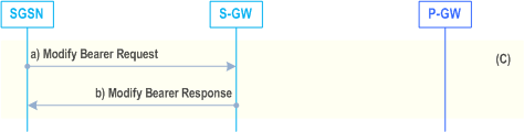

Box (C).
Step 10 is identical to the Gn/Gp case in clause 6.13.2.2.1, except that:
- Message SGSN Context Request is replaced by message Context Request;
- Parameter PDP Contexts is replaced by parameter EPS Bearer Contexts. MM Context and EPS Bearer Context when used at the S16 interface are defined by clause 13.2.2.
![]()
![]()
![]()