Content for TS 23.002 Word version: 18.0.0
5.17 Configuration of Home (e)NodeB entities
5.18 Configuration for facilitating communications with packet data networks and applications
5.19 Configuration of Packet Switched Streaming (PSS) Service
5.20 Configuration of Proximity-based Services
5.21 Configuration for RAN user plane congestion detection and reporting
...
...
5.17 Configuration of Home (e)NodeB entities |R9| p. 76
5.17.1 Configuration of the Home NodeB Subsystem p. 76
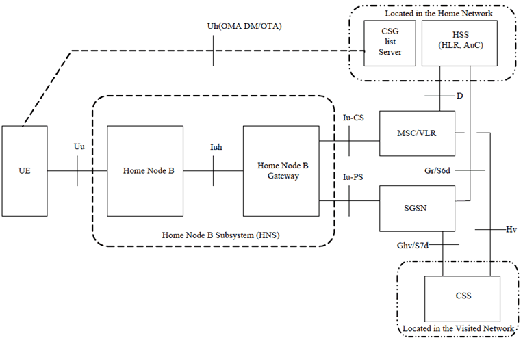
The configuration of the Home NodeB Subsystem is presented in Figure 5.17-1. In the Figure, all the functions are considered implemented in different logical nodes. If two logical nodes are implemented in the same physical equipment, the relevant interfaces may become internal to that equipment.
The Home NodeB Gateway may also be used only for the control plane of Iu-CS and/or Iu-PS interfaces. In this case, the user plane of Iu-CS and/or Iu-PS interfaces is directly between the Home NodeB and respectively the MSC/VLR and the SGSN/Serving GW/GGSN.
In case Direct Tunnel is established, the user plane is directly between the Home NodeB Subsystem and the GGSN or Serving GW nodes.

Figure 5.17-1: Configuration of PLMN supporting Home NodeB Subsystem
(⇒ copy of original 3GPP image)
(⇒ copy of original 3GPP image)
5.17.2 Configuration of the Home eNodeB Subsystem p. 77
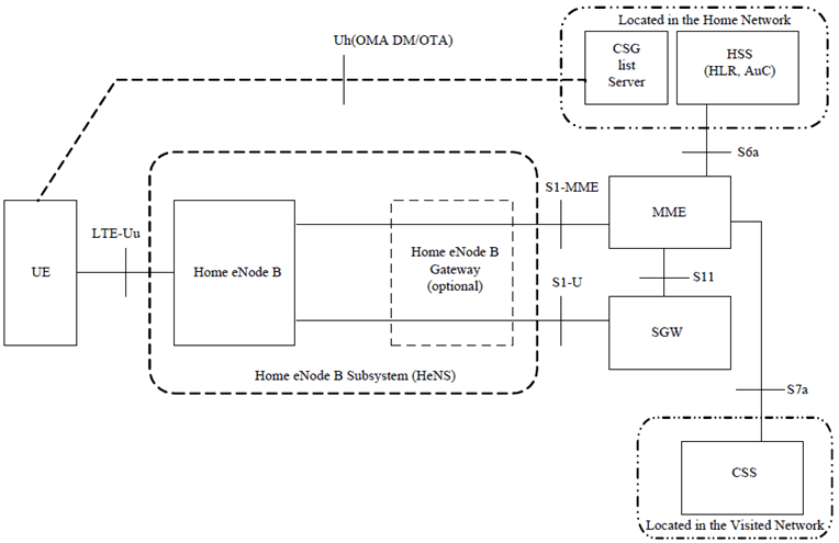
The configuration of Home eNodeB Subsystem with a Home eNodeB Gateway present is shown in Figure 5.17-2. In the Figure, all the functions are considered implemented in different logical nodes. If two logical nodes are implemented in the same physical equipment, the relevant interfaces may become internal to that equipment.
The presence of Home eNodeB Gateway in the configuration of Home eNodeB Subsystem is optional.
The Home eNodeB Gateway may also be used only for the S1-MME interface. In this case, the S1-U interface is directly between the Home eNodeB and the S-GW.

Figure 5.17-2: Configuration of PLMN supporting Home eNodeB Subsystem
(⇒ copy of original 3GPP image)
(⇒ copy of original 3GPP image)
5.18 Configuration for facilitating communications with packet data networks and applications |R11| p. 78
The reference architecture model, the reference points and the functional entities to facilitate communications with packet data networks and applications are described in TS 23.682.
5.19 Configuration of Packet Switched Streaming (PSS) Service |R12| p. 78
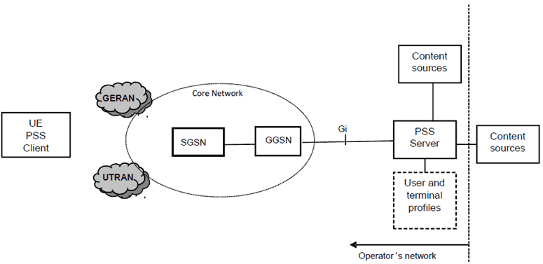
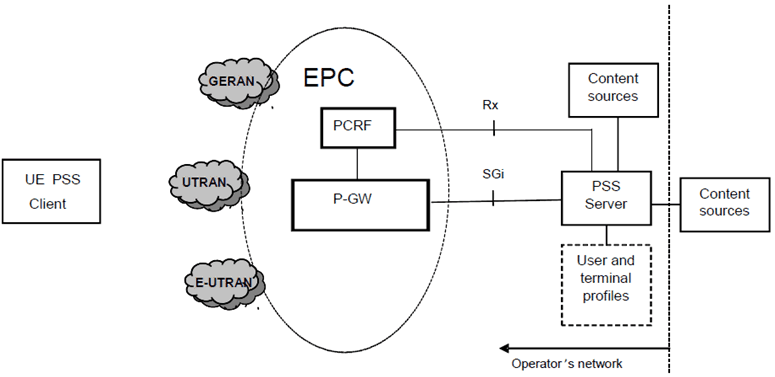
The configuration of the PSS entities for GPRS and EPS is represented in Figure 5.19-1 and Figure 5.19-2 respectively. PSS for GPRS supports UTRAN and GERAN. PSS for EPS supports E-UTRAN, UTRAN and GERAN. Further details of the PSS Service are described in TS 26.233.


5.20 Configuration of Proximity-based Services |R12| p. 79
The reference architecture model, the reference points and the functional entities to facilitate ProSe are described in TS 23.303.
5.21 Configuration for RAN user plane congestion detection and reporting |R13| p. 79
RAN user plane congestion detection and reporting enables the PCRF to take the RAN user plane congestion status into account for policy decisions. This functionality is applicable only in case of UTRAN/E-UTRAN accesses. The configuration of the related entities is depicted in Figure 5.21.

Figure 5.21: Configuration for RAN user plane congestion detection and reporting
(⇒ copy of original 3GPP image)
(⇒ copy of original 3GPP image)